


. . . . . . . . . . . . . . . . . . . . . . . . . . . . . .
1-6 Overview
Writer: Fran Spragens Project: Overview Comments: 355307-002
File Name:3324_1.doc Last Saved On:3/16/99 11:31 AM
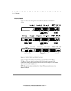
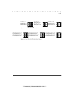
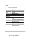
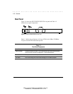
Table 1-1 defines the front panel components.
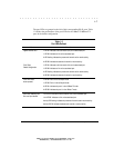
Table 1-1
Front Panel Components
Name Function
100Base-FX Fiber Ports (Ports 1
and 2)(SW3323 with fiber card
pre-installed)
Multi-mode fiber ports used with SC fiber connectors. Indicates Link and
Activity information.
Gigabit Ethernet ports 25 and 26
LEDs (SW3324)
Indicates Link and Activity information
1000Base-X Gigabit Ethernet ports
SW3324)
Gigabit Ethernet ports using GBIC modules
Fiber Ports 1 and 2 LEDs
(SW3323 with fiber card
pre-installed)
Indicates Link and Activity information (see Table 1-2 for details).
Ports 1-24 RJ-45 LEDs (SW3322)
Indicates Link, Activity, Speed and Duplex information (see Table 1-2
for details).
LED mode button
Button used to switch RJ-45 port LEDs between Link/Activity mode and
100M/Full Duplex mode. This button has no affect when using Multi-mode
fiber Ports 1 and 2 (SW3323).
Power LED
Lights steady green to indicate power is supplied to the switch. Off
indicates no power is supplied to the switch.
Test LED Lights steady green after a reset and remains on until successful
completion of power-on self tests. Off indicates a successful completion of
the power-on self tests.
Console port
DB-9 connector configured as a null modem connection for serial out-of-
band management using the console menus.