E-10
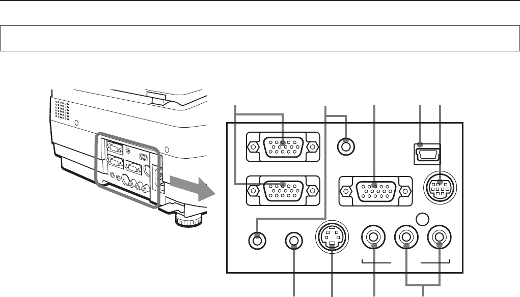
Names and Functions of the Parts (Input/Output Connectors)
TEST
PC AUDIO
IN2
PC AUDIO
IN1
PC AUDIO
OUT
S-VIDEO
VIDEO
RGB-OUT
RGB-IN 2
RGB-IN 1
V
L R
USB
1
2 3 5
6
7 8 9
4
A Check of the Supplied Items and the Names of the Parts
1. PC Video Input
Input terminal for the PC analog RGB signals. Two per-
sonal computers can be connected. See Page E-16.
2. PC Audio Input
Audio input terminal for a PC (stereo compatible). Two per-
sonal computers can be connected. See Page E-16.
3. RGB Video Output
When OHP is selected, OHP images are output. When
PC/VIDEO input is selected, input PC video is output as it
is. During standby, RGB-IN1 images that are input from the
personal computer are output directly. See Page E-16.
4. USB connector
This connector is used for USB connections with a per-
sonal computer.
Please see the "iP Viewer Software Program Operating In-
structions".
5. Test (maintenance) connector
This special connector is used at the time of maintenance
and factory tests. It cannot be used for other connections.
6. Audio Output
Audio output terminal for projector.
This terminal outputs audio (either from the PC or video
source) that is currently being input. In the standby mode,
PC audio is output. When OHP input is selected, PC audio
is output.
See Page E-16.
7. S-VIDEO Input
Input terminal for video source (Y/C).
See Page E-20.
8. Video Source Video Input
Input terminal for video source (NTSC/PAL/SECAM).
See Page E-20.
9. Video Source Audio Input
Audio input terminals for a video source (stereo compatible).
See Page E-20.


