


MTEK6000 SERIES USER'S MANUAL
2-2 January 2002
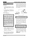
NOTE
The flashing LCD display indicates an
alarm condition (e.g. First Time Power).
See Chapter 3 for information on alarms.
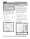
8. You can now view selected parameter
values on the display by using the scroll
switch. The scroll switch is activated by
the use of a magnet (one is shipped with
the unit). See Display Mode, in Chapter
3, for information about this function.
POWER FOR THE MTEK6000
Two 4.5V alkaline battery packs (part #
1011-0035C-001) supply operating power to
the device for approximately two years of
typical operation. Recommended operating
temperature range for the MTEK6000 when
powered with these packs is –4 F (-20 C) to
130 F (54 C). If this supply should fail, an
on-board back-up battery will maintain the
unit's memory and real time clock. Backup
power can maintain history data for up to
seven years. When back-up power is used,
the unit discontinues normal operation until
the main battery pack is replaced.
Note that only one power source powers
the MTEK6000; connection of battery
packs to a unit configured for external
power does not provide an additional
source of backup power for the unit.
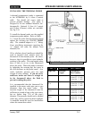
Optional Power Supplies
Several optional supplies are available:
A. Two Single-D Lithium battery packs -
(part # 1011-0039B-001) provides an
approximate life expectancy of two years
over the temperature range -22
0
F (-30
0
C)
to 158
0
F (70
0
C). Each 3.6V, 13.0 AH
battery pack can be used individually (~
1yr life) or as a pair.
B. MTEK6000 UPS power supply - an un-
interruptible 12 VDC power supply with
battery back up.
C. SPS 50 solar system - 10 to 64 W systems
available with battery backup; while
selected system size depends on
geographic location, degree of sun
exposure, equipment power consumption,
and site obstructions, most MTEK6000
applications only require a 10W system.
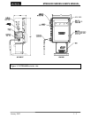
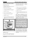
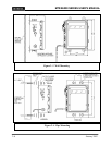
MOUNTING THE INSTRUMENT ON
THE METER
1. Check the meter's rotation direction.
Standard setup is clockwise rotation of the
meter output shaft, as viewed from the top.
The rotation of the unit can be changed to
counterclockwise. Also, the input drive
value for the unit can be changed.
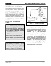
2. Align the instrument's index base plate
holes with the corresponding holes in the
meter's index base plate. Secure the unit
by bolting it to the meter. Ensure that the
drive dogs are correctly aligned and not
binding.
3. Plug all unused holes in the index base
plate with the caps provided in the
accessory package.