


MTEK6000 SERIES USER'S MANUAL
January 2002 4 - 3
MTEK6000 ANALOG OUTPUT
SPECIFICATIONS
Environmental
Operating Temperature -30°C to + 70°C
or -22°F to 158°F
Operating Humidity 0 to 95%
noncondensing
Electrical Isolation
500 V DC or AC RMS (sine wave) between
digital interface and 4-20 mA loop.
Current Loop Output
Maximum Output Current 24mA
Minimum Output Current 3.5mA
Maximum Supply Voltage 50V
Minimum Supply Voltage 8V
Resolution 16 bits, 0.00024 mA
Full Scale %Error ±0.01% max
(software calibrated at
4 and 20 mA and tested
at room temperature)
Temperature Drift ±0.00044 mA/
°
F
max
Error caused by RFI <1% of span shift
with 2.8W 150MHz
applied at 1.7’
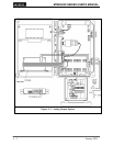
Installing the Analog Output Loop
A ribbon cable connects the AO module to
the display / analog board. Commands are
sent to the module via the cable by the
MTEK6000 device. The 4-20mA current
loop is a simple two-wire connection. +24
volts DC nominal is connected to the “+”
terminal (pos. 1) and the “-”, or return
terminal (pos. 2), is connected to the field
instrument to which the 4-20mA signal is
being sent.
Calibrating the Analog Output
Several features make the Analog Output
software calibration routine attractive and
more intuitive. In the MTEK6000 device,
unit calibration can be software-based; there
is no need for laborious operator
adjustments. Software calibration does
away with the need for repetitive
potentiometer adjustments, thereby
simplifying field calibration procedures.
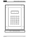
The display / keypad or Meter Reader
Virtual Keypad software are necessary to
perform software calibration.
NOTE
Pressing esc repeatedly from anywhere
within the calibration procedure will back
the operator out of calibration mode.
1. Display the Analog Output parameter on
the inside display. The common
function key assignment for Analog
Output #1 is F6, and F7 for Analog
Output #2.
2. Press cal. Enter your password at the
optional PASSWORD? prompt, if
required.
3. The unit will enter calibration mode and
the display will show the current value
and mA representation of the analog
output signal. For example,
Eng: 48.000
mA: 11.680
where 48.000 is the analog output reading
representing 11.680 mA. The top line will
alternate between four different readouts
Eng: 48.000, UP/DN TO CHANGE,
CALIBRATING, and the parameter label
(Analog Output #1 in this case), while the
bottom line will always show the mA value.
4. Connect a multimeter in series with the
loop to measure the current. The field
instrument which the loop is driving can
also be used to read the output if desired.
5. Pressing ↑ will increment the output
current to represent 0%, 25%, 50%,
75%, & 100% of the analog output
parameter to check the calibration.
Pressing ↓ will decrement the output
current.