


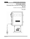


MTEK6000 SERIES USER'S MANUAL
January 2002
Analog Sampling ……..................................................................……..…. 3-8
Special Key Combinations …………………............................................... 3-9
Assigning The Number of Displayed Digits .............................................. 3-9
Viewing and Clearing Alarms from the Keypad ....................................... 3-9
Calibration Mode ........................................................................................... 3-10
Calibrating the Pressure Transducer ....................................................... 3-10
Calibrating the Temperature Transducer .................................................. 3-11
Calibrating the Differential Pressure Transducer ...................................... 3-12
Section 4: Optional Equipment 4-1
Analog Output …………............................................................................... 4-1
MTEK6000 Analog Output Specifications …...................................................... 4-3
Installing the Analog Output Loop …............................................................. 4-3
Calibrating the Analog Output …................................…............................... 4-3
Section 5: Maintenance and Software Packages 5-1
Enclosure Maintenance ............................................................................... 5-1
Changing the Battery ................................................................................... 5-1
Calibration .................................................................................................... 5-1
PcGas Meter Reader …................................................................................. 5-2
PcGas Meter Utility ……................................................................................ 5-2
PcGas Customer Monitor .............................................................................. 5-2
MTEK Manager.................................................................................... ......... 5-2
DC2000 ........................................................................................................ 5-3
Appendix A : Process Configuration Standard A-1
Appendix B : Calculations B-1
Appendix C : Parameter Description C-1
Appendix D : Board Jumper Positions D-1
Appendix E : Certifications (CSA, UL, FCC drawings / statements) E-1
Appendix F : Warranty Information F-1
Appendix G : TII Telephone Circuit Surge Suppressor G-1
Appendix H : Hazardous Area Installation Control Drawings H-1