


MTEK6000 SERIES USER'S MANUAL
2-10 January 2002
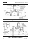
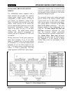
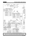
INSTALLING THE PULSE OUTPUT
WIRING
The MTEK6000 comes standard with a
board installed that provides two optically
isolated pulse outputs. These outputs are
configurable as either Form C or Form A
type outputs. An alternative version of the
board is available that provides four pulse
outputs. Both versions of the board also
provide terminal block positions to access the
uncorrected mechanical volume switch
output of the index. See Fig. 2-11 for pulse
output wiring. The option boards optical
coupling and physical arrangement of
circuitry provide a minimum of 1,500 volts
of isolation.
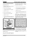
Wiring connections for the pulse outputs are
made from terminals 19 to 17 for Pulse
output #1, terminals 16 to 14 for Pulse output
#2, terminals 13 to 11 for Pulse output #3 and
terminals 10 to 8 for Pulse output #4. See
Fig. 2-11 for pulse output wiring location and
Form C vs. Form A jumpering. Note that
proper operation of the Form C pulse output
configuration requires that a constant wetting
current be available at both the normally open
and normally closed terminals by the device
attached to that pulse output.
The corrected volume pulse output generated
can be scaled to any desired volume value.
Typical values are 10, 100, 1,000, or 10,000
cubic feet per pulse, or the metric equivalents.
The scaling factor is selected by the Pulse
Out CF Per Pulse parameters. The pulse
duration (width) is also configurable up to
5,000 ms. The Pulse Output On-Time and
Off-Time parameters determine the pulse
time for corrected volume, uncorrected
volume and pressure corrected volume pulses.
The Alarm Pulse Time (ms) parameter
determines the pulse time for alarm outputs.
See Appendix C in this manual or Meter
Reader Help screen for description of this
parameter.
Figure 2- 9 Pulse Output Wiring