


MTEK6000 SERIES USER'S MANUAL
2-12 January 2002
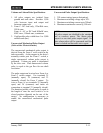
COMMUNICATIONS
To communicate with the MTEK6000, the
Site ID (RUID) in the device must be the
same as the Site ID entered in the software
package. The Site ID is a unique
identification number (1 to 65,535) that
allows the Metretek, Inc. software packages
to communicate with the MTEK6000. The
default Site ID number is 1. Software can be
used to enter a number other than the default.
Refer to the respective software User’s
Manual for additional information on these
and other functions. The optional external
display and keypad can also be used to
change the Site ID from its default value.
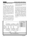
RS-232C Serial (Direct) Communications
(9600 Baud)
In its standard configuration, the MTEK6000
is equipped with one RS-232C serial port.
An optional RS-232C serial cable (Part #
1002-0235C-001) is required for direct
communications. The serial port allows an
operator to configure and collect data with an
industry-standard (IBM
, Compaq
, etc.)
portable computer (software is required for
this function). The MTEK6000
communicates at 9600 baud with portable or
host computers connected directly to the
serial port. When communicating with the
MTEK6000, Busy will be displayed on the
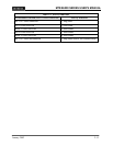
display. Table 2-2 shows the diagnostic
features of the Activity indicator when the
cable is connected.
WARNING
The MTEK6000 will not go to sleep if the
RS-232C serial cable is left connected and
battery life will be affected drastically.
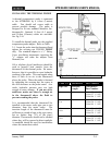
Modem Communications (2400 Baud)
NOTE
This modem complies with Part 68 of the
FCC Rules. See Appendix E for details.
The internal Hayes compatible modem offers
automatic answering and dialing. The modem
communicates at 2400/1200/300 baud. The
modem by itself can only be used in areas
classified as non-hazardous or Class I,
Division 2. To maintain the MTEK6000’s
intrinsic safety classification in more
hazardous areas such as Class I, Division 1, an
optional Phone Line Interface (PLI) must be
used. This device removes the high voltage
ring-detect circuitry from the device and
brings low-level signals into the hazardous
area through intrinsic safety barriers.
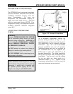
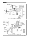
Connecting the Telephone Line
If the MTEK6000 is situated in a non-
hazardous or Class I, Division 2 area, connect
the tip and ring wires from the telephone
company's terminal box to the TIP and RING
terminals (1 and 2 respectively).
If it is installed in a Class I, Division 1, Group
D area, install the unit per the reference
drawing shown Appendix E. Also see
Appendix D for proper jumper settings.
Installation of the phone line surge protection
device provided with the MTEK6000 is
strongly recommended when the MTEK6000s
internal modem is connected to a telephone
line. The device is a separate gas tube type
phone line surge suppressor and is housed in
its own enclosure suitable for mounting
directly to a telephone pole or other structure.