


MTEK6000 SERIES USER'S MANUAL
D-2 January 2002
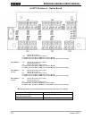
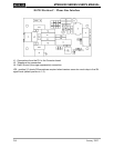
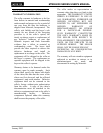
61-OPT Revision A – Option Board
Pulse Output 1: Use Terminal 19 (normally open contact)
Terminal 18 (common 1)
and Terminal 17 (normally closed contact)
For form A output: put JP1 and JP1A both in position A to B.
For form C output: put JP1 and JP1A both in position B to C (requires external wetting).
Pulse Output 2: Use Terminal 16 (normally open contact)
Terminal 15 (common 2)
and Terminal 14 (normally closed contact)
For form A output: put JP2 and JP2A both in position A to B.
For form C output: put JP2 and JP2A both in position B to C (requires external wetting).
Pulse Output 3 : Use Terminal 13 (normally open contact)
(optional) Terminal 12 (common 3)
and Terminal 11 (normally closed contact)
For form A output: put JP3 and JP3A both in position A to B.
For form C output: put JP3 and JP3A both in position B to C (requires external wetting).
Pulse Output 4: Use Terminal 10 (normally open contact)
(optional) Terminal 9 (common 4)
and Terminal 8 (normally closed contact)
For form A output: put JP4 and JP4A both in position A to B
For form C output: put JP4 and JP4A both in position B to C (requires external wetting).
JP5 can be used as a convenient means to connect pulse input 2 as follows:
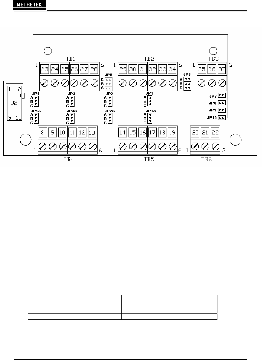
Description Jumper position
connect pulse input 2 to mechanical
index secondary output
JP5 A, B, & C all in
otherwise JP 5 A, B, & C all out (default)