


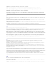
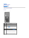
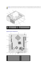

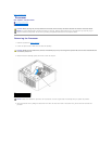

Inside Your Computer
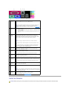
1
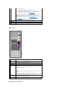
parallel
connector
Connect a parallel device, such as a printer, to the parallel connector. If
you have a USB printer, plug it into a USB connector.
NOTE: The integrated parallel connector is automatically disabled if the
computer detects an installed card containing a parallel connector
configured to the same address. For more information, see System Setup
Options.
2
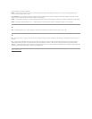
link integrity
light
l Green — A good connection exists between a 10-Mbps network
and the computer.
l Orange — A good connection exists between a 100-Mbps network
and the computer.
l Off — The computer is not detecting a physical connection to the
network.
3
network
adapter
connector
To attach your computer to a network or broadband device, connect one
end of a network cable to either a network jack or your network or
broadband device. Connect the other end of the network cable to the
network adapter connector on the back panel of your computer. A click
indicates that the network cable has been securely attached.
NOTE: Do not plug a telephone cable into the network connector.
On computers with a network adapter card, use the connector on the
card.
It is recommended that you use Category 5 wiring and connectors for
your network. If you must use Category 3 wiring, force the network
speed to 10 Mbps to ensure reliable operation.
4
network
activity light
This light flashes yellow when the computer is transmitting or receiving
network data. A high volume of network traffic may make this light
appear to be in a steady "on" state.
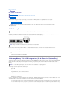
5
line-in
connector
Use the blue line-in connector to attach a record/playback device such as
a cassette player, CD player, or VCR.
On computers with a sound card, use the connector on the card.
6
line-out
connector
Use the green line-out connector to attach headphones and most
speakers with integrated amplifiers.
On computers with a sound card, use the connector on the card.
7
microphone
connector
Use the pink microphone connector to attach a personal computer
microphone for voice or musical input into a sound or telephony program.
On computers with a sound card, the microphone connector is on the
card.
8
USB 2.0
connectors
(4)
Use the back USB connectors for devices that typically remain connected,
such as printers and keyboards.
9
video
connector
Plug the cable from your VGA-compatible monitor into the blue connector.
NOTE: If you purchased an optional graphics card, this connector will be
covered by a cap. Connect your monitor to the connector on the graphics
card. Do not remove the cap.
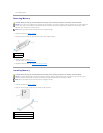
10
serial
connector
Connect a serial device, such as a handheld device, to the serial port.
The default designation is COM1 for serial connector 1.
For more information, see System Setup Options.
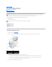
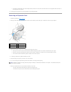
CAUTION: Before you begin any of the procedures in this section, follow the safety instructions located in the Product Information Guide.