


The E600i System | 13
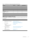
E600i System Installation Process
To install the E600i system, Dell Force10 recommends that you perform the installation procedures in the
following order:
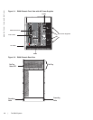
Table 3-1. E600i Hardware Component Operating Requirements Summary
Component Minimum Maximum Field-Replaceable
Backplane (factory installed) 1 1 N
Air filter (factory installed) 1 1 Y
Fan tray* 1 1 Y
RPMs 1 2 Y
Line cards 1 7 Y
SFMs 4 5 Y
Power Supplies:
2500 AC Power Supply OR
DC PEMs
2
1
4
2
Y
Y
Cable management system 0 1 Y
Cable management system cover 0 1 Y
*Fan tray is field replaceable, but must be replaced within 1 minute of removing it.
Step Task Section
1 Prepare the site
Site Preparation
2 Unpack the chassis and components
Unpacking the E600i System
3 Mount the chassis
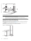
Standard Front Chassis Rack Mounting
Installing the Chassis into an Equipment Cabinet
4 Install components:
• Fan tray
• AC Power Supply or DC PEMs
(including power cables)
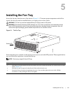
Installing the Fan Tray
Power Supply
5 Install card components:
• RPM(s) and line cards
• SFMs
Preparing and Installing the RPMs and Line Cards
Installing Switch Fabric Modules (SFMs)
6 Connect network cable
RPM Ports and Cables
7 Supply power to the chassis
Powering Up