26 | Power Supply
www.dell.com | support.dell.com
Replace the DC PEM
The PEM Status LED is unlit or amber if the unit fails. In this case, replace the entire unit. There are no
field serviceable parts inside the PEM unit.
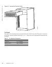
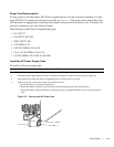
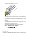
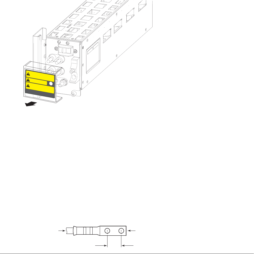
3 Loosen the retaining screw and remove PEM safety cover (
Figure 6-6
).
Figure 6-6. Removing the DC PEM Safety Cover
4 Slide the backplane connector end of the PEM into Power Supply Slot 1 or 3. Secure the PEM to the chassis by
tighten the two locking screws.
5 Secure the chassis ground connection:
Remove one outer nut and one washer from each of the six studs. The inner nut should remain tight on the stud, at
no more than 25 inch-lbs.
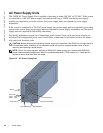
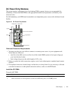
Locate the chassis ground connector studs on the PEM front panel (see
Figure 6-5
). The two bottom studs are the
ground connection.
Attach the grounding cable onto the ground studs. The grounding cable must comply with your local electrical
codes in size and color (typically the color is green or green with yellow stripe), and the grounding cable must be
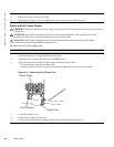
terminated only with a UL-listed 2-hole lug with 1/4-inch holes on 3/4-inch spacing (see
Figure 6-7
).
Replace the two washers and nuts.
With a 7/16-inch box or socket wrench, tighten the nuts to 25 in-lbs.
Connect the opposite end of the grounding cable to the nearest appropriate facility grounding post.
Figure 6-7. Cable Connector for DC Power Entry Modules
C
A
U
T
IO
N
-
T
u
r
n
o
ff
p
o
w
e
r
s
o
u
r
c
e
c
ir
c
u
it
b
r
e
a
k
e
r
b
e
fo
r
e
a
c
c
e
s
s
in
g
te
rm
in
a
ls
.
A
C
H
T
U
N
G
-
V
e
r
je
d
e
r W
a
r
tu
n
g
H
a
u
p
ts
c
h
a
lte
r
Always replace safety cover
after servicing
Do not plug in while energized.
C
A
U
T
IO
N
-
Unit may have more than one power
source connection. Remove all supply connections
C
C
-E
60
0
-C
V
R
-P
E
M
0.750
High-strand-count
conductor
diamete
r
2 Holes
0.267


