


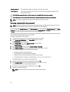
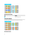

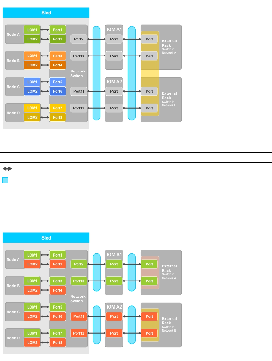
Figure 6. Network adapter isolation configuration
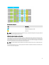
Icon Description
Network path
Single trunk configuration or LAG
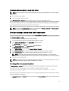
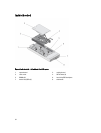
Isolated networks configuration
In this configuration, each of the two LOMs on a node is mapped to separate I/O modules and external rack switches, to
provide maximum redundancy. The two external switches are on separate networks in this configuration.
Figure 7. Isolated networks configuration
28