


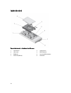
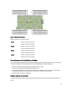
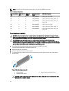
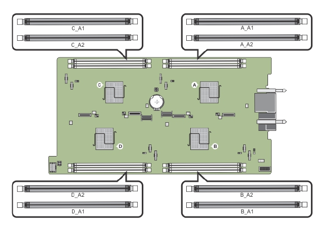
Figure 13. Memory socket locations
Memory channels are organized as follows:
Node A channel 1: memory socket A_A1
channel 2: memory socket A_A2
Node B channel 1: memory socket B_A1
channel 2: memory socket B_A2
Node C channel 1: memory socket C_A1
channel 2: memory socket C_A2
Node D channel 1: memory socket D_A1
channel 2: memory socket D_A2
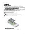
General memory module installation guidelines
Your system supports Flexible Memory Configuration, enabling the system to be configured and run in any valid chipset
architectural configuration. The following are the recommended guidelines for optimal performance:
• Memory modules must be of the same type and capacity for all the nodes.
• At least one memory module must be populated for each node.
• The memory configuration for each node must be identical. For example, if you populate socket A_A1 for node A,
then populate socket B_A1 for node B, socket C_A1 for node C, and socket D_A1 for node D.
• Mixing of memory modules is not supported.
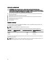
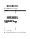
Sample memory configurations
The following table shows sample memory configurations that follow the appropriate memory guidelines stated in this
section.
37