


Back to Contents Page
System Board Assembly
Dell™OptiPlex™FX160/160ServiceManual
System Board Connectors
Removing the System Board Assembly
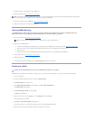
Replacing the System Board
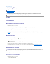
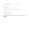
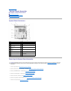
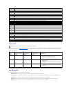
System Board Connectors
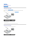
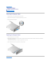
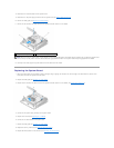
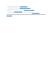
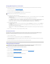
Removing the System Board Assembly
1. Perform the procedure in Before Working on Your Computer.
2. Remove the hard drive bracket assembly, if installed (Removing the Hard Drive Bracket Assembly).
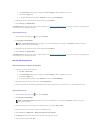
3. Remove the NVRAM module, if installed (see Removing the NVRAM Module).
4. Remove the wireless card, if installed (see Removing the Wireless Card).
5. Remove the memory module(s) (see Removing a Memory Module).
6. Remove the processor heatsink assembly (see Removing the Processor Heatsink Assembly).
7. Remove the I/O board (see Removing the I/O Board).
1
memory connector (DIMM_1)
2
memory connector (DIMM_2)
3
battery (BATTERY)
4
audio connector (AUDIOF1)
5
USB connector (USBF1)
6
setup jumper (SETUP_LOCK)
7
front panel connector
(FRONTPANEL)
8
SATA data cable connector (SATA_1)
9
NVRAM module connector
(SATA_0)
10
clear CMOS jumper (RTCRST)
11
clear password jumper
(PSWD)
12
WLAN connector (MINIA1)
13
fan connector (FAN_CPU)
14
screw holes (3)
15
12V power connector (PWR1)
16
SATA hard-drive power connector
(SATAPWR1)
17
CPU
CAUTION: BIOS options setup in a new system board may not be the same as those setup on the system board you are replacing. To retain the
same BIOS option settings, record the current system BIOS option settings for future reference. Refer to BIOS Setup Utility Options for more
information.