


8. Disconnect the I/O board cables from the system board.
9. Disconnect the 12V power supply connector from the system board (see System Board Connectors).
10. Remove the cable guide (see Removing the Cable Guide).
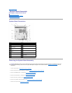
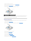
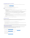
11. Remove the two screws on the back corners of the system board that secure it to the chassis.
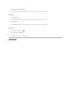
12. Carefully lift the front edge of the system board remove the board from the chassis.
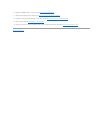
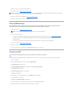
Replacing the System Board
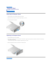
1. Move the system board into the chassis at about a 30-degree angle, aligning the connectors on the back edge of the board with the cutouts on the
back panel, then lower the system board into place.
2. Replace the cable guide (see Replacing the Cable Guide).
3. Replace the two screws on the back corners of the system board that secure it to the chassis (see System Board Connectors).
4. Connect the 12V power supply connector to the system board.
5. Replace the I/O board (see Replacing the I/O Board).
6. Connect the I/O board cables to the system board.
7. Replace the cable guide (see Replacing the Cable Guide)
8. Replace the memory module(s) (see Replacing a Memory Module).
9. Replace the wireless card if it was removed (see Replacing the Wireless Card).
1
cable guide retaining screw
2
system board retaining screw (2)
NOTE: When removing the system board from the chassis, the thermal gap pad between the chassis and the processor may not allow the system board
to lift out freely. You may have to break the bond between the gap pad and the bottom of the system board. Keep the gap pad with the chassis.