


1-16
'HOO2SWL3OH[*;*;S0DQDJHG3&DQG2SWL3OH[1;1HW3&6\VWHPV6HUYLFH0DQXDO
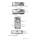
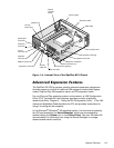
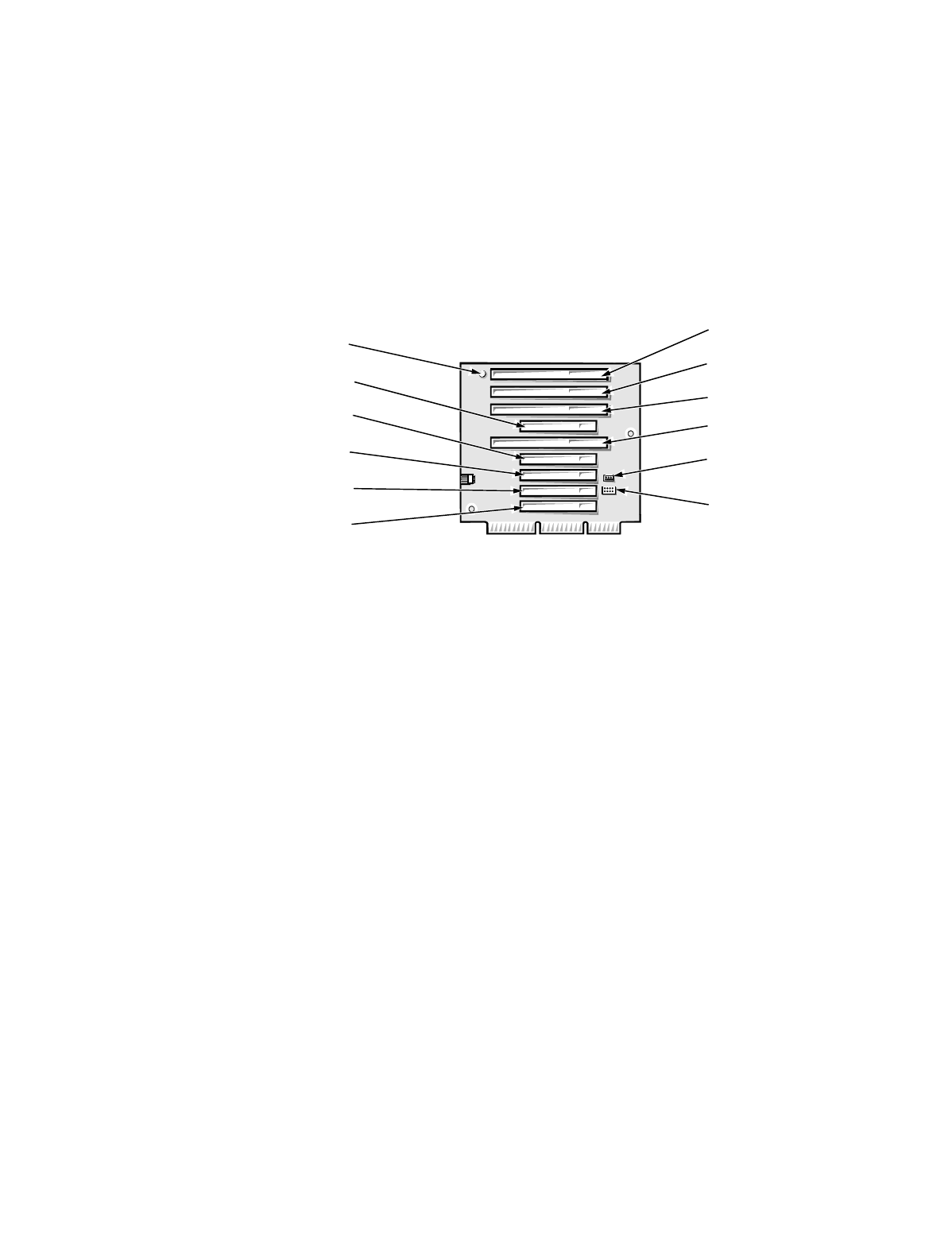
0LQL7RZHU&RPSXWHU ·V([SDQVLRQ&DUG6ORWV
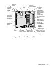
The OptiPlex GX1/GX1p mini tower computers have seven expansion-card
slots. The riser board has four ISA expansion-card connectors and five PCI
expansion-card connectors. Two PCI expansion-card connectors share
expansion-card slots with two ISA connectors, resulting in a total of seven
expansion-card slots (see Figure 1-11). The riser board is active, incorporating
PCI-to-PCI bridging.
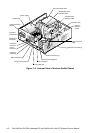
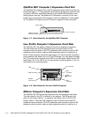
The mini tower riser board includes the P1 connector (for connecting the NIC
to the riser board cable) and an LED. If the LED is on, the riser board is receiv-
ing power; if off, the riser board is not receiving power.
)LJXUH5LVHU%RDUGIRUWKH0LQL7R ZH U&RPSXWH U
8SJUDGH2SWLRQV
The system board has various accommodations for system upgrades
including:
Microprocessor upgrade
Main memory expansion
Video memory expansion
These upgrades are summarized in the following subsections, and installation
procedures are provided for the various chassis configurations in Chapters 4, 5,
6, and 7.
0LFURSURFHVVRU/&DFKH8SJU DGHV
On the OptiPlex GX1/GX1p and OptiPlex NX1 systems, the microprocessor
and secondary L2 cache memory are implemented in an SEC cartridge/heat
sink assembly. Upgrade to a higher-performance microprocessor is accom-
plished by snapping out the old assembly and installing an upgrade assembly
as higher-performance microprocessors become available.
ISA4
ISA1
HDLED
connector
P1 connector
PCI1
PCI5
ISA2
PCI2
PCI3
ISA3
LED
PCI4