


1-18
'HOO2SWL3OH[*;*;S0DQDJHG3&DQG2SWL3OH[1;1HW3&6\VWHPV6HUYLFH0DQXDO
6\VWHP'LDJQRVWLFV
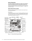
Server-based and diskette-based diagnostics are available to aid in troubleshoot-
ing all major components of the OptiPlex GX1 and GX1p. The OptiPlex NX1
systems use server-based diagnostics, hard-disk–based diagnostics, or the
diskette-based diagnostics using an external diskette-drive kit connected directly
to the system board. See “Running the System Diagnostics” in Chapter 2 for
additional information.
6\VWHP%RDUG6HUYLFH'DWD
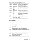
The following subsections provide service-related information about the sys-
tem board and components.
6\VWHP%RDUG
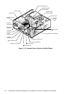
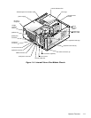
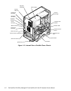
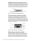
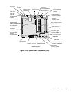
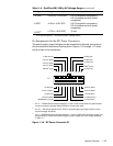
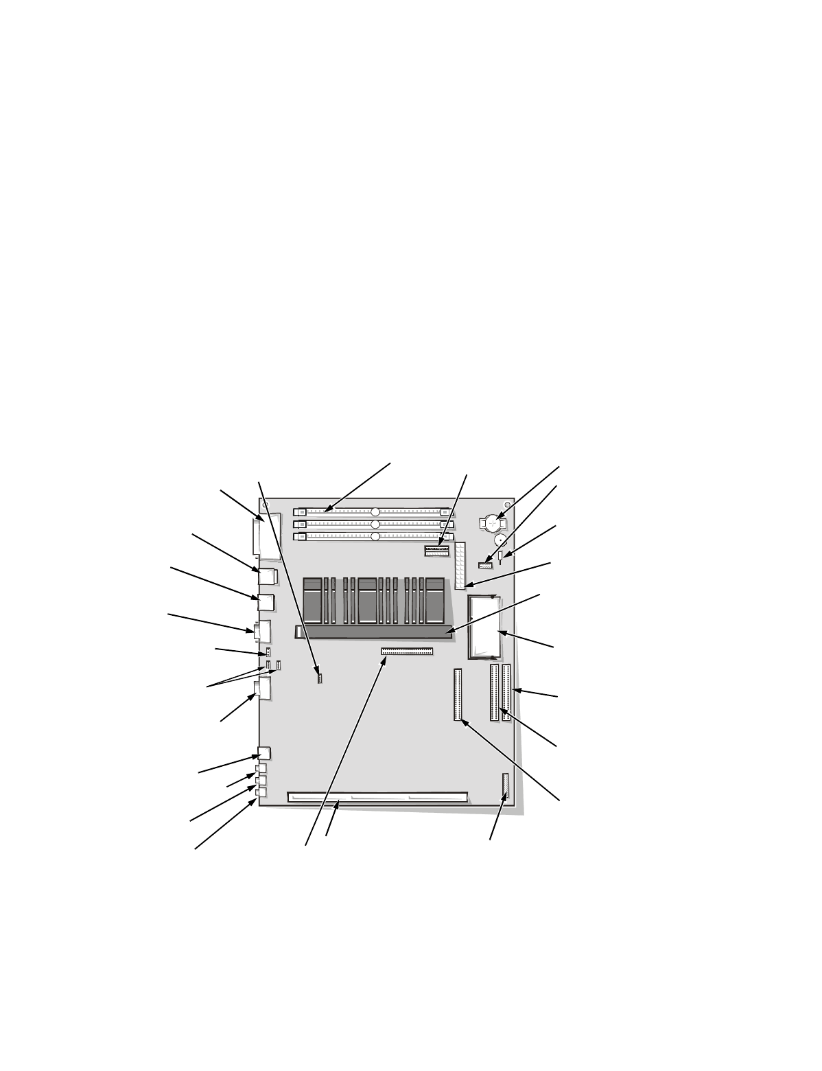
The OptiPlex GX1p, and newer versions of the GX1 and OptiPlex NX1 systems
use the system board shown in Figure 1-12 (integrated NIC is optional on the
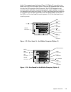
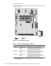
GX1 and NX1). Older versions of the OptiPlex GX1 and OtiPlex NX1 systems
use the system board shown in Figure 1-13.
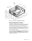
)LJXUH6\VWHP%RDUG&RP S RQHQWV1HZ
& $%
SEC cartridge connector
(SLOT1)
microprocessor
fan connector (FAN)
microphone jack (MIC)
video
connector MONITOR)
serial port 2
connector
(SERIAL2)
USB connectors
(USB) (2)
parallel/serial port 1
connectors (stacked)
(PARALLEL/SERIAL1)
mouse/keyboard
connectors (stacked)
(MOUSE/KYBD)
audio line-in
jack (LINE-IN)
audio line-out
jack (LINE-OUT)
video-memory
upgrade socket
(VIDEO_UPGRADE)
control panel
connector (PANEL)
battery socket
(BATTERY)
optional
integrated NIC
connector (ENET)
riser board connector (RISER)
system board jumpers
primary EIDE
interface connector
(IDE1)
secondary EIDE
interface connector
(IDE2)
front of computer
diskette/tape drive
interface connector
(DSKT)
DIMM sockets (3)
(DIMM_A–DIMM_C)
main power input
connector (POWER_1)
3.3-V power
input connector
(POWER_2)
ATI multimedia
connector (AMC)
CD-in
connectors (CD-IN)
telephony
connector
(TAPI)
chassis intrusion
switch connector