


1-30
'HOO2SWL3OH[*;*;S0DQDJHG3&DQG2SWL3OH[1;1HW3&6\VWHPV6HUYLFH0DQXDO
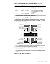
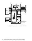
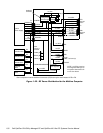
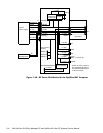
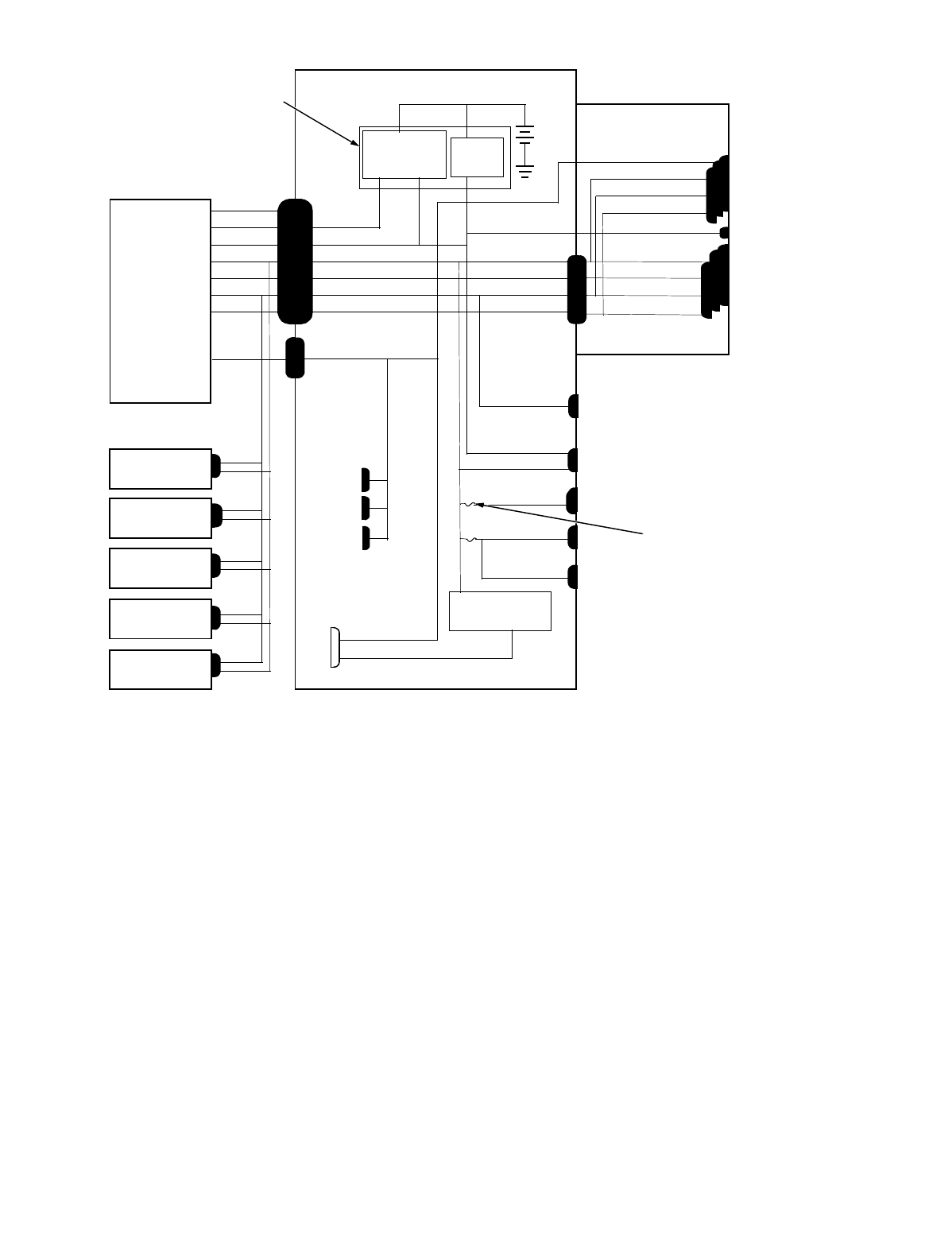
)LJ X UH'&3RZHU'LVWULEXWLRQIRU WKH0LGVL]H&RPSXWHU
–12 VDC
power
management
and NIC logic
P7
+3.3 VDC
POWER1
system
power supply
RTC/
NVRAM
+3.3 VDC
+5 VDC
+5 VDC
+5 VDC
+5 VDC
+5 VFP
+12 VDC
–12 VDC
+5 VDC
–5 VDC
+12 VDC
–12 VDC
+5 VDC
–5 VDC
PSON#
+5 VFP
+5 VDC
–5 VDC
+12 VDC
PWRGOOD
PSON#
+5 VFP
+5 VDC
–5 VDC
+12 VDC
–12 VDC
+3 VDC
keyboard
controller
P3
+5 VDC
+12 VDC
–12 VDC
+12 VDC
3.5-inch
diskette drive
battery
P1
ISA1
through
ISA3
PCI1
through
PCI3
MICROPROCESSOR
PANEL
KYBD
MOUSE
DIMM_A
DIMM_B
main
memory
sockets
P4
FAN
RISER
internal
hard-disk drive
P2
optional
drive
P5
*
P6
*
riser board
system board
optional
drive
internal
hard-disk drive
processor
core regulator
POWER2
core VCC +2.1 to +3.5 VDC
USB
+3.3 VDC
*
Some computers have an additional connector (P9) that may be used instead of P5 or P6.
fuses (2)
+5 VFP
P1
DIMM_C
NOTE: +5 VFP is routed to
the integrated NIC logic on
the system board and to P1
on the riser board.