


1-32
'HOO2SWL3OH[*;*;S0DQDJHG3&DQG2SWL3OH[1;1HW3&6\VWHPV6HUYLFH0DQXDO
.
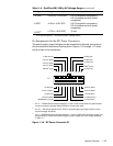
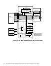
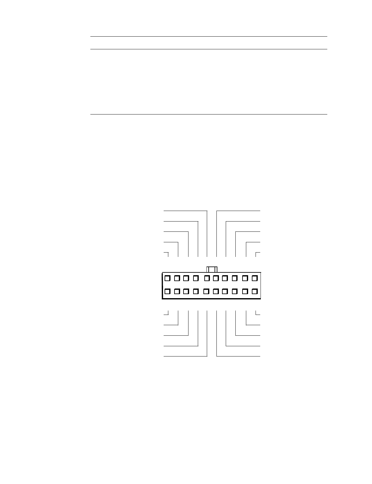
2SWL3OH[1;3LQ$VVLJQPHQWVIRUWKH'&3RZHU&RQQHFWRUV
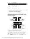
The power-supply output voltages can be measured at the back (wire side) of
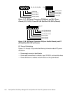
the connectors without disconnecting them. Figures 1-24 through 1-26 show
the wire side of the connectors.
1
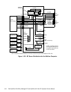
Pin 11 — PSON# should measure between +4 and +5 VDC except when the power button
on the front panel is pressed, taking PSON# to its active-low state.
2
Pin 19 — Thermal fan-speed control (TFSC) is a power-supply input signal used to control
the power-supply fan speed.
3
Pin 5 — PWRGOOD should measure between +4 and +5 VDC when the power supply is
on to indicate that all power-supply output voltages are within the ranges specified in
Table 1-5.
)LJXUH'&3RZHU&RQQHFWRU3IRUWKH2S WL3OH[1;&RPSXWHU
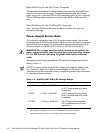
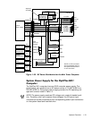
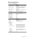
7DEOH2SWL3OH[1;'&9ROWDJH5DQJHV
9ROWDJH 5DQJH
0D[LPXP2XWSXW&XUUHQW
1
+3.3 VDC +3.14 to +3.47 VDC
6.0 A
1
+5 VDC +4.75 to +5.25 VDC
12.0 A
1
+12 VDC +11.40 to +12.60 VDC
1.0 A
2
–12 VDC –10.80 to –13.20 VDC 0.5 A
+5 VFP
3
+4.75 to +5.25 VDC 1.2 A
1
The combined load on the +5-VDC and +3.3-VDC outputs should not exceed 65 W.
2
Withstands surges of up to 3.0 A to support disk start-up operations.
3
VFP (volts flea power) — sometimes called “standby power.”
11
1
PWRGOOD
3
(orange)
–12 VDC (blue)
+12 VDC (yellow)
+5 VFP (purple)
common (black)
234 5678 910
12 13 14 15 16 17 18 19 20
3
+5 VDC (red)
+5 VDC (red)
+5 VDC (red)
+5 VDC (red)
+5 VDC (red)
+5 VDC (red)
common (black)
common (black)
common (black)
PSON#
1
(gray)
common (black)
common (black)
common (black)
open
TFSC
2
(brown)