


Removing and Replacing Parts 4-35
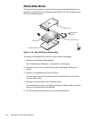
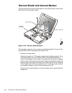
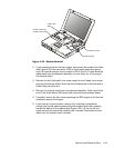
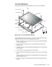
)LJXUH0RGHP5HPRYDO
2. If your computer has an internal modem, disconnect the modem flex cable
(see Figure 4-23) from connector JP20 on the system board and discon-
nect the twisted wire pair from connector JP2 on the RJ-11 card. Bend the
cables back over the palmrest assembly to move them out of the way of
the thermal shield.
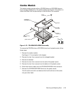
3. Remove the four flat-head 4-mm screws and the one K-head 4-mm screw
securing the thermal shield. Note that the K-head screw is leftmost and is
thicker than the other four.
4. Remove the thermal shield from the palmrest assembly. Note that the bot-
tom of the shield has an EMI fence that surrounds the processor board.
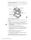
5. If needed, remove the two screws securing the EMI fingers to the thermal
shield and remove the fingers.
6. If you have an internal modem, remove it by inserting a screwdriver
through the circular opening and pulling the modem carrier box carefully
toward the back of the computer (see Figure 4-23). Lift the top off the
metal carrier and remove the modem card if needed. Disconnect the flex
cable from the modem card if needed.
modem flex
cable
circular opening
modem carrier box
(modem card inside)
twisted wire pair