


4-60
'HOO,QVSLURQ6HUYLFH0DQXDO
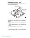
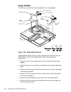
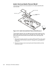
+LQJH6DGGOHV
This section provides the removal procedure for the hinge saddles.
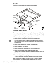
DGGOH
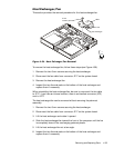
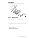
)LJXUH+LQJH6DGGOH5HPRYDO
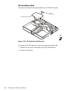
This procedure assumes that you have removed the PC Card heat sink and
LVDS board. To remove the hinge saddles, follow these steps (see
Figure 4-40):
1. Remove the four 4-mm screws from the top of the left and right hinge
saddles.
2. Remove the four 4-mm screws from the back of the computer above the
ports.
3. Remove the 10-mm screw and 20-mm screw from the right hinge saddle
and remove the saddle.
4. Remove the 10-mm screw and 20-mm screw from the left hinge saddle
and remove the saddle.
5. Disconnect the LED cable from connector J6 on the system board.
6. Remove the 6-mm screw from the plastic frame, remove any tape, and
remove the plastic frame.
6-mm screw (1)
left hinge saddle
right hinge
saddle
plastic
frame
4-mm screws (4)
LED
cable
20-mm
screws (2)
10-mm screws (2)
4-mm screws (4)