


4-50
'HOO,QVSLURQ6HUYLFH0DQXDO
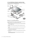
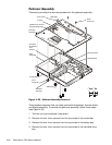
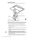
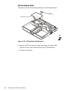
7RXFK3DG$VVHPEO\
This section provides the removal procedure for the touch pad assembly.
)LJXUH7RXFK3DG$VVHPEO\5HPRYDO
This procedure assumes that you have removed the palmrest assembly from
the base assembly and that you have removed the hard-disk drive heat shield.
To remove the touch pad assembly, follow these steps (see Figure 4-33):
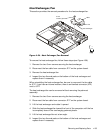
1. Remove the three 4-mm screws securing the touch pad button board.
2. Disconnect the two speaker cables from connectors JP5 and JP3 on the
touch pad button board.
3. Disconnect the speaker wire harness from connector JP1 on the touch pad
button board.
4. Disconnect the touch pad flex cable from ZIF connector JP4 on the touch
pad button board. Use the pick to pry up the latches on each side of the
connector.
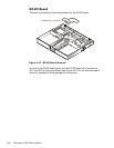
&$87,21/LIWDZD\WKHFDEOHRQO\DIWHUWKH=,)FRQQHFWRULV
RSHQHGVHH´=,)&RQQHFWRUVµIRXQGHDUOLHULQWKLVFKDSWHU3XOO
LQJWKHFDEOHIURPWKHFRQQHFWRUGDPDJHVWKHFRQGXFWLYHFRDWLQJ
RQWKHHQGRIWKHFDEOH
5. Disconnect the touch pad flex cable from ZIF connector J1 on the touch
pad. Use the pick to pry up the brown center piece on the connector.
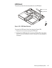
touch pad
touch pad bracket
touch pad
button board
4-mm
screws (3)
4-mm screws (4)
touch pad
flex cable
ZIF connector