


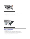

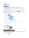
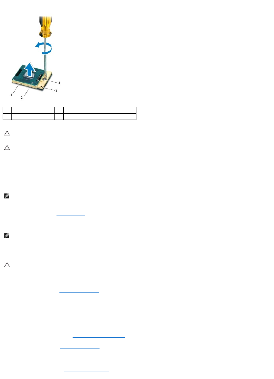
16. Lift the processor module off the ZIF socket.
Replacing the Processor Module
1. Follow the instructions in Before You Begin.
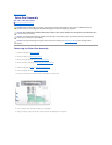
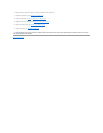
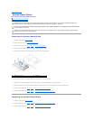
2. Align the pin-1 corner of the processor module with the pin-1 corner of the ZIF socket.
3. Place the processor module lightly in the ZIF socket and ensure that the processor module is positioned correctly.
4. Tighten the ZIF socket by turning the cam screw clockwise to secure the processor module to the system board.
5. Replace the heat sink (see Replacing the Heat Sink).
6. Follow the instructions from step 11 to step 15 in Replacing the Top Cover.
7. Replace the bluetooth card (see Replacing the Bluetooth Card).
8. Replace the Mini-Card(s) (see Replacing the Mini-Card(s)).
9. Replace the display assembly (see Replacing the Display Assembly).
10. Replace the keyboard (see Replacing the Keyboard).
11. Replace the palm-rest assembly (see Replacing the Palm-Rest Assembly).
12. Replace the optical drive (see Replacing the Optical Drive).
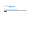
1
ZIF socket
2
processor module
3
pin-1 corner
4
ZIF-socket cam screw
CAUTION: To ensure maximum cooling for the processor module, do not touch the heat transfer areas on the processor thermal-cooling assembly.
The oils in your skin can reduce the heat transfer capability of the thermal pads.
CAUTION: When removing the processor module, pull the module straight up. Be careful not to bend the pins on the processor module.
NOTE: If a new processor module is installed, you will receive a new thermal-cooling assembly, which will include an affixed thermal pad, or you will
receive a new thermal pad along with documentation to illustrate proper installation.
NOTE: The pin-1 corner of the processor module has a triangle that aligns with the triangle on the pin-1 corner of the ZIF socket.
CAUTION: To avoid damage to the processor module, hold the screwdriver perpendicular to the processor module when turning the cam screw.