


English- 17
Pr. Explanation Settings
Factory
Setting
NOTE
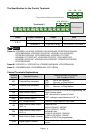
03.05 Terminal Count
Value
0 to 9999 0
03.06
Preliminary Count
Value
0 to 9999 0
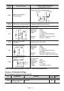
03.07
EF Active When
Terminal Count
Value Attained
0: Terminal count value attained, no EF
display
1: Terminal count value attained, EF active
0
03.08 Fan Control
0: Fan always ON
1: 1 minute after AC motor drive stops, fan
will be OFF
2: Fan ON when AC motor drive runs, fan
OFF when AC motor drive stops
3: Fan ON when preliminary heatsink
temperature attained
0
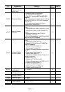
03.09
The Digital Output
Used by PLC
(NOT for VFD*E*C
models)
Read only
Bit0=1:RLY used by PLC
Bit1=1:MO1 used by PLC
Bit2=1:MO2/RA2 used by PLC
Bit3=1:MO3/RA3 used by PLC
Bit4=1:MO4/RA4 used by PLC
Bit5=1:MO5/RA5 used by PLC
Bit6=1:MO6/RA6 used by PLC
Bit7=1:MO7/RA7 used by PLC
##
03.10
The Analog Output
Used by PLC
(NOT for VFD*E*C
models)
Read only
Bit0=1:AFM used by PLC
Bit1=1: AO1 used by PLC
Bit2=1: AO2 used by PLC
##
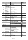
03.11
Brake Release
Frequency
0.00 to 20.00Hz 0.00
03.12
Brake Engage
Frequency
0.00 to 20.00Hz 0.00
03.13
Display the Status of
Multi-function
Output Terminals
Read only
Bit0: RLY Status
Bit1: MO1 Status
Bit2: MO2/RA2 Status
Bit3: MO3/RA3 Status
Bit4: MO4/RA4 Status
Bit5: MO5/RA5 Status
Bit6: MO6/RA6 Status
Bit7: MO7/RA7 Status
##
03.14 Desired Frequency
2 Attained
0.00 to 600.0Hz 0.00
Group 4 Input Function Parameters
a04.00
Keypad
Potentiometer Bias
0.0 to 100.0 % 0.0
a04.01
Keypad
Potentiometer Bias
Polarity
0: Positive bias
1: Negative bias
00
a04.02
Keypad
Potentiometer Gain
0.1 to 200.0 % 100.0