


English- 4
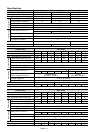
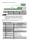
Storage/ Transportation
Temperature
-20
o
C to 60
o
C
Ambient Humidity Below 90% RH (non-condensing)
Vibration 9.80665m/s
2
(1G) less than 20Hz, 5.88m/s2 (0.6G) at 20 to 50Hz
Approvals
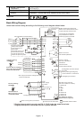
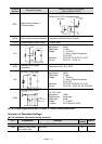
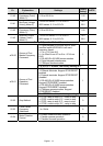
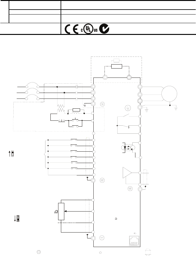
Basic Wiring Diagram
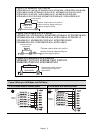
Users must connect wiring according to the following circuit diagram shown below.
AVI
ACI
ACM
+
4~20mA
+10V
5K
3
2
1
Power supply
+10V 3mA
Master Frequency
0 to 10V 47K
Analog Signal Common
E
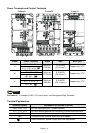
Main circuit (power) terminals
Control circuit terminals
Shielded leads & Cable
* Don't apply the mains voltage directly
to above terminals.
E
R(L1)
S(L2)
T(L3)
Fuse/NFB(None Fuse Breaker)
SA
OFF
ON
MC
MC
RB
RC
Recommended Circuit
when power supply
is turned OFF by a
fault output
If the fault occurs, the
contact will be ON to
turn off the power and
protect the power system.
R(L1)
S(L2)
T(L3)
E
Analog Multi-function Output
Terminal
factory setting: Analog freq.
/ current meter
0~10VDC/2mA
U(T1)
V(T2)
W(T3)
IM
3~
AFM
ACM
RA
RB
RC
Motor
Factory setting:
Drive is in operation
48V50mA
Multi-function
Photocoulper Output
Analog Signal common
E
E
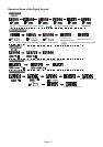
Refer to Control
Terminal Explanation
MO1
MCM
MI1
MI2
MI3
MI4
MI6
MI5
DCM
+24V
FWD/Stop
REV/Stop
Multi-step 1
Multi-step 2
Multi-step 3
Multi-step 4
Digital Signal Common
Factory
setting
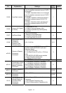
Sw2
AVI
ACI
Factory setting:
ACI Mode
ACI/AVI switch
When switching to AVI,
it indicates AVI2
-
8
1
Sw1
NPN
PNP
Factory setting:
NPN Mode
Please refer to following
figure for wiring of NPN
mode and PNP mode.
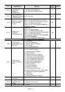
Brake resistor/unit (optional)
Refer to user manual for the use
of special brake resistor/unit.
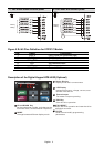
The wiring for the models
may be different. Refer to
following figures for detail.
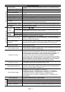
* Single-phase models can only use R(L1), S(L2) to be the power terminals.
* Single-phase power cannot be used for 3-phase models.
BUE
Brake unit
(optional)
BR
brake resistor
(optional)
RS-485 serial interface
(NOT for VFD*E*C models)
1: Reserved
2: EV
5: SG+
6: Reserved
7: Reserved
8: Reserved
3: GND
4: SG-
For VFD*E*C models,
please refer to figure 5.