


English- 18
Pr. Explanation Settings
Factory
Setting
NOTE
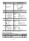
04.03
Keypad
Potentiometer
Negative Bias,
Reverse Motion
Enable/Disable
0: No negative bias command
1: Negative bias: REV motion enabled
0
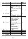
04.04 2-wire/3-wire
Operation Control
Modes
0: 2-wire: FWD/STOP, REV/STOP
1: 2-wire: FWD/REV, RUN/STOP
2: 3-wire operation
0
1
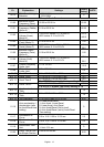
04.05 Multi-function Input
Terminal (MI3)
2
04.06 Multi-function Input
Terminal (MI4)
3
04.07 Multi-function Input
Terminal (MI5)
0: No function
1: Multi-Step speed command 1
2: Multi-Step speed command 2
3: Multi-Step speed command 3
4: Multi-Step speed command 4
5: External reset
6: Accel/Decel inhibit
7: Accel/Decel time selection command
8: Jog Operation
9: External base block
10: Up: Increment master frequency
11: Down: Decrement master frequency
12: Counter Trigger Signal
13: Counter reset
14: E.F. External Fault Input
15: PID function disabled
16: Output shutoff stop
17: Parameter lock enable
18: Operation command selection (external
terminals)
19: Operation command selection(keypad)
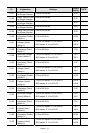
04.08
Multi-function Input
Terminal (MI6)
For VFD*E*C
models, the factory
setting is 23. The
factory setting for
the other models is
4.
20: Operation command
selection(communication)
21: FWD/REV command
22: Source of second frequency command
23: Run/Stop PLC Program (PLC1) (NOT
for VFD*E*C models)
23: Quick Stop (Only for VFD*E*C models)
24: Download/execute/monitor PLC Program
(PLC2) (NOT for VFD*E*C models)
25: Simple position function
26: OOB (Out of Balance Detection)
27: Motor selection (bit 0)
28: Motor selection (bit 1)
04.09
Multi-function Input
Contact Selection
Bit0:MI1
Bit1:MI2
Bit2:MI3
Bit3:MI4
Bit4:MI5
Bit5:MI6
Bit6:MI7
Bit7:MI8
Bit8:MI9
Bit9:MI10
Bit10:MI11
0