


English- 6
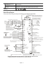
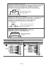
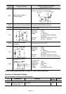
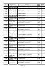
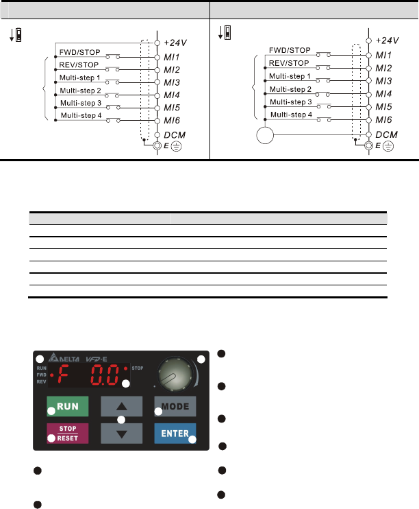
C. PNP mode without external power D. PNP mode with external power
Sw1
Factory
setting
NPN
PNP
Sw1
Factory
setting
NPN
PNP
24
Vdc
-
+
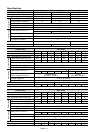
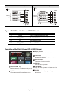
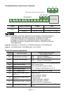
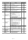
Figure 5 RJ-45 Pins Definition for VFD*E*C Models
PIN Signal Description
1 CAN_H CAN_H bus line (dominant high)
2 CAN_L CAN_L bus line (dominant low)
3 CAN_GND Ground / 0V /V-
4 SG+ 485 communication
5 SG- 485 communication
7 CAN_GND Ground / 0V /V-
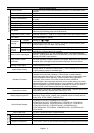
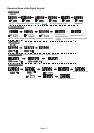
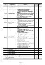
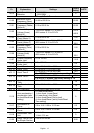
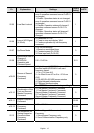
Description of the Digital Keypad KPE-LE02 (Optional)
LED Display
Indicates frequency, voltage, current, user
defined units and etc.
Status Displa
y
Display the driver's current status.
STOP/RESET
Stops AC drive operation and reset the drive
after fault occurred.
RUN Key
Start AC drive operation.
MODE
Change between different display mode.
UP and DOWN Key
Set the parameter number and changes the
numerical data, such as Master Frequency.
Potentiometer
For master Frequency setting.
1
2
3
4
5
6
7
2
3
4
5
6
7
8
8
ENTER
Used to enter/modify programming
parameters
1