


10 Jackrabbit (BL1800)
2.2.2 Connect Programming Cable
The programming cable connects the Jackrabbit to the PC running Dynamic C to down-
load programs and to monitor the Jackrabbit during debugging.
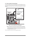
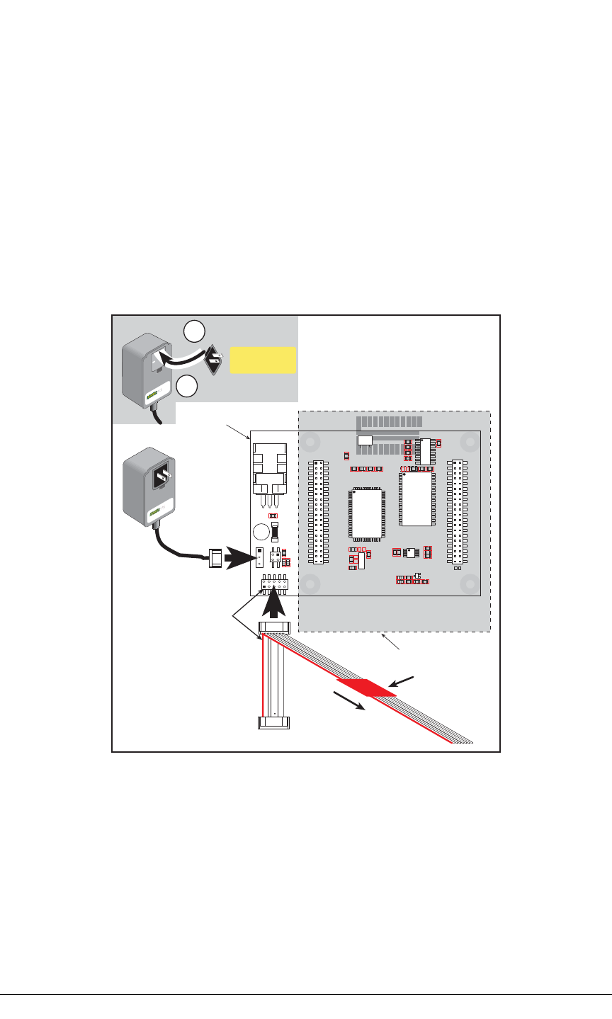
Connect the 10-pin connector of the programming cable labeled PROG to header J3 on
the Jackrabbit board as shown in Figure 2. Be sure to orient the marked (usually red) edge
of the cable towards pin 1 of the connector. (Do not use the DIAG connector, which is used
for a normal serial connection.)
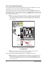
NOTE: Use only the programming cable that has a red shrink wrap around the RS-232
level converter (Part No. 20-101-0513), which is supplied with the Development Kit.
Other Rabbit programming cables are not voltage-compatible or their connector sizes
may be different.
Figure 2. Power and Programming Cable Connections
to Jackrabbit Board
NOTE: Never disconnect the programming cable by pulling on the ribbon cable.
Carefully pull on the connector to remove it from the header.
Connect the other end of the programming cable to a COM port on your PC.
NOTE: Some PCs now come equipped only with a USB port. It may be possible to use
an RS-232/USB converter (Part No. 20-151-0178) with the programming cable sup-
plied with the Jackrabbit Development Kit. Note that not all RS-232/USB converters
work with Dynamic C.
PROTOTYPING BOARD
JACKRABBIT BOARD
JP1
U4
VIN GNDGND
RESET
JACKRABBIT
Z-World, Inc.
GND
PA0
PA2
PA4
PA6
GND
PB0
PB2
PB4
PB6
WDO
GND
PE6
PE4
PE2
PE0
HV0
HV2
K
GND
VCC
PA1
PA3
PA5
PA7
GND
PB1
PB3
PB5
PB7
PCLK
PE7
PE5
PE3
PE1
GND
HV1
HV3
+RAW
VCC
GND
RXC
TXC
PC1
PC3
PC5
PC7
AGND
DA1
PD1
PD3
PD5
PD7
GND
485+
VCC
SM1
STAT
VBAT
GND
VCC
RXB
TXB
PC0
PC2
PC4
PC6
AD0
DA0
PD0
PD2
PD4
PD6
GND
485
VCC
SM0
IOBEN
GND
/RST
J5
U6
U5
U3
J4
U1
J1
J2
J3
Y3
Rabbit 2000
SRAM
RS-232
RS-485
Colored side
lines up with
pin 1
Remove slot cover,
insert tab into slot
Snap plug into place
2
1
Assemble
AC Adapter
To
PC COM port
PROG
DIAG
Programming
connector
Diagnostic
connector
Red
shrink wrap