User’s Manual 21
3.3 A/D Converter
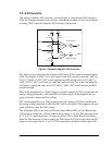
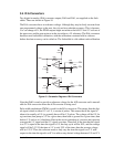
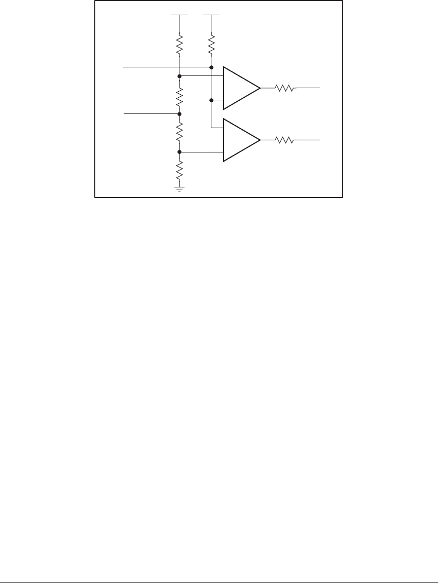
The analog-to-digital (A/D) converter, shown in Figure 9, compares the DA0 voltage to
AD0, the voltage presented to the converter. DA0 therefore cannot be used for the digital-
to-analog (D/A) converter when the A/D converter is being used.
Figure 9. Schematic Diagram of A/D Converter
The A/D converter transforms the voltage at DA0 into a 20 mV window centered around
DA0. For example, if DA0 is 2.0 V, the window in
the A/D
converter would be 1.990 V to
2.010 V. If AD0 > 2.010 V, PE7 would read high and PE6 would read low. If 1.990 V <
AD0 < 2.010 V, PE7 would read low and PE6 would read low. This is the case when the
A/D input is exactly the same as DA0. If AD0 < 1.990 V, PE7 would read low and PE6
would read high.
PE6 can be imagined to be a “DA0 voltage is too high” indicator. If DA0 is larger than the
analog voltage presented at AD0, then PE6 will be true (high). If this happens, the pro-
gram will need to reduce the DA0 voltage.
PE7 can be imagined to be a “DA0 voltage is too low” indicator. If DA0 is smaller than
the analog voltage presented at AD0, then PE7 will be true (high). If this happens, the pro-
gram will need to raise the DA0 voltage.
The A/D input, AD0, is the same as DA0 only when PE6 and PE7 are low. Because the
A/D converter circuit uses a 20 mV window, the accuracy is ±10 mV. DA0 can range from
0.1 V to 2.8 V, which represents 270 steps of ±10 mV. This is better than 8-bit accuracy.
Since the D/A converter is able to change the DA0 output in 3.88 mV steps, there are 697
steps over the range from 0.1 V to 2.8 V. This represents a resolution of more than 9 bits.
+
+
Vcc
Vcc
LM324
LM324
R31
10 kW
R34
51.1 kW
AD0
DA0
R35
200 W
R33
200 W
R32
51.1 kW
9
10
13
12
14
8
R36
R30
0 W
0 W
DA0 too high
DA0 too low
PE6
PE7


