


User’s Manual 25
either a 0% or a 100% duty cycle. The duty cycle is programmed as the high-time count of
1024 total counts of the Rabbit 2000’s timer B. Thus, 256 counts would be 25% of 1024
counts, and corresponds to a 25% duty cycle.
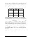
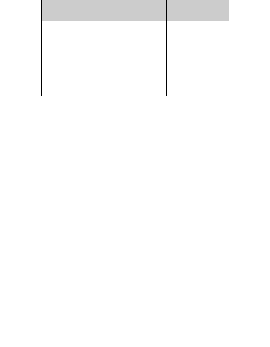
Table 2 lists typical DA1 voltages measured for various duty cycle values with a load
larger than 1 MΩ.
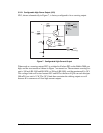
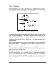
It is important to remember that the DA1 output voltage will not be realized instanta-
neously after programming in a value. There is a settling time because of the RC time con-
stant (R24 × C22), which is 10 ms. For example, the voltage at any given time is
V = V
P
– (V
P
– V
DA1
)e
(-t/RC)
(EQ 1)
where V is the voltage at time t, V
P
is the programmed voltage, V
DA1
is the last DA1 out-
put voltage from the D/A converter, and RC is the time constant (10 ms). The settling will
be within 99.326% (or within about 21 mV for a 3 V change in voltage) after five time
constants, or 50 ms. Six time constants, 60 ms, will allow settling to within 99.75% (or to
within about 8 mV for a 3 V change in voltage). Seven time constants, 70 ms, will allow
settling to within 99.91% (or to within about 3 mV for a 3 V change in voltage).
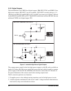
An LM324 op amp, which can comfortably source 10 mA throughout the D/A converter
range, drives the D/A converter output. If the output voltage is above 1 V, the D/A con-
verter can comfortably sink 10 mA. Below 1 V, the D/A converter can only sink a maxi-
mum of 100 µA.
To summarize, DA1 is provided uncalibrated, can be programmed with a resolution of
5 mV and a peak-to-peak ripple less than 20 mV over the range from 0.7 V to 3.5 V and
0 V. The settling time to within 21 mV is 50 ms.
Table 2. Typical DA1 Voltages for Various Duty Cycles
Duty Cycle
(%)
Voltage
(V)
Programmed Count
0 0.002 0–122
12 0.620 123
25 1.242 256
50 2.483 512
72 3.567 742
100 3.567 743–1024