User’s Manual 77
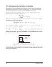
Once the LEDs, resistors, and switches are disconnected as described above, the user has a
Jackrabbit board with connection points conveniently brought out to labeled points at headers
J3 and J7 on the Prototyping Board. Small to medium circuits can be prototyped using point-
to-point wiring with 20 to 30 AWG wire between the prototyping area and the holes at loca-
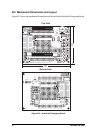
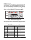
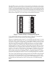
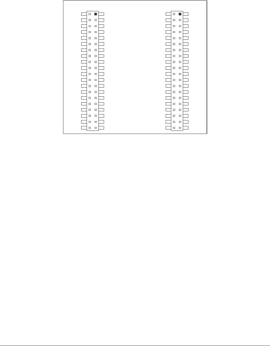
tions J3 and J7. Note that the pinouts at locations J3 and J7 on the top side of the Prototyping
Board (shown in Figure B-7) are a mirror image of the Jackrabbit board pinouts.
Figure B-7. Jackrabbit I/O Pinout on Prototyping Board (top side)
A user-supplied DE9 connector can be added as shown in Figure B-3. The signals are
brought out to location J5 on the top side of the Prototyping Board.
There are six independent surface-mount 14- to 16-pin SOIC pads and fourteen 3- to 5-pin
SOT23 pads. Each component has every one of its pin pads connected to a hole in the pro-
totyping area. The layout is such that there is another SOIC or SOT23 pad directly on the
other side of the PCB from the SOIC or SOT23 pads. However, each layout location is
routed to its unique set of connection holes. Because the traces are very thin, carefully
determine which set of holes is connected to which surface-mount pad. There are several
standard 0805 passive-component surface-mount pads. These pads are not routed to wir-
ing holes so wire must be soldered directly to the component. In addition, there is a large
generic array of wide traces connected to large holes. This is provided as an additional
area for surface-mount passive components. There is a moderate amount of 0.1” arrayed
through-hole prototyping area (about 137 holes) for mounting through-hole components.
Thus, many circuits requiring special circuitry external to the Jackrabbit can be prototyped
and tested with the Prototyping Board. If additional prototyping space is needed, install
40-pin headers at locations J3 and J7 on the top side of the Prototyping Board to connect
to sockets that you would install at J3 and J7 on the top side of a second Prototyping
Board.
J7
VCC
PA1
PA3
PA5
PA7
GND
PB1
PB3
PB5
PB7
PCLK
PE7
PE5
PE3
PE1
GND
HV1
HV3
+RAW
VCC
J3
GND
PA0
PA2
PA4
PA6
GND
PB0
PB2
PB4
PB6
WDO
GND
PE6
PE4
PE2
PE0
HV0
HV2
K
GND
VCC
RXB
TXB
PC0
PC2
PC4
PC6
AD0
DA0
PD0
PD2
PD4
PD6
GND
485
VCC
SM0
IOBEN
GND
/RST
GND
RXC
TXC
PC1
PC3
PC5
PC7
AGND
DA1
PD1
PD3
PD5
PD7
GND
485+
VCC
SM1
STAT
VBAT
GND


