


32 Jackrabbit (BL1800)
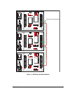
3.6 Programming Cable
The programming cable is used to connect the Jackrabbit’s programming port to a PC serial
COM port. The programming cable converts the RS-232 voltage levels used by the PC
serial port to the TTL voltage levels used by the Rabbit 2000.
When the PROG connector on the programming cable is connected to the Jackrabbit’s
programming header, programs can be downloaded and debugged over the serial interface.
The DIAG connector of the programming cable may be used on the Jackrabbit’s program-
ming header with the Jackrabbit operating in the Run Mode. This allows the programming
port to be used as a regular serial port.
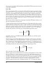
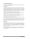
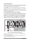
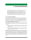
3.6.1 Changing Between Program Mode and Run Mode
The Jackrabbit is automatically in Program Mode when the
PROG connector on the pro-
gramming cable is attached to the Jackrabbit, and is automatically in Run Mode when no
programming cable is attached. When the Rabbit 2000 is reset, the operating mode is
determined by the status of the SMODE pins. When the programming cable’s
PROG
connector is attached, the SMODE pins are pulled high, placing the Rabbit 2000 in the
Program Mode. When the programming cable’s PROG connector is not attached, the
SMODE pins are pulled low, causing the Rabbit 2000 to operate in the Run Mode.
Figure 13. Jackrabbit Program Mode and Run Mode Setup
A program “runs” in either mode, but can only be downloaded and debugged when the
Jackrabbit is in the Program Mode.
Refer to the
Rabbit 2000 Microprocessor User’s Manual for more information on the pro-
gramming port and the programming cable.
JP1
Program Mode
JP1
Run Mode
Power
RESET Jackrabbit board when changing mode:
Short out RESET pads below header J5,
OR
Press RESET button (if using Prototyping Board), OR
Cycle power off/on
after removing or attaching programming cable.
Reset pads
Reset pads
U4
U4
VIN GNDGND
RESET
JACKRABBIT
Z-World, Inc.
GND
PA0
PA2
PA4
PA6
GND
PB0
PB2
PB4
PB6
WDO
GND
PE6
PE4
PE2
PE0
HV0
HV2
K
GND
VCC
PA1
PA3
PA5
PA7
GND
PB1
PB3
PB5
PB7
PCLK
PE7
PE5
PE3
PE1
GND
HV1
HV3
+RAW
VCC
GND
RXC
TXC
PC1
PC3
PC5
PC7
AGND
DA1
PD1
PD3
PD5
PD7
GND
485+
VCC
SM1
STAT
VBAT
GND
VCC
RXB
TXB
PC0
PC2
PC4
PC6
AD0
DA0
PD0
PD2
PD4
PD6
GND
485
VCC
SM0
IOBEN
GND
/RST
J5
U6
U5
U3
J4
U1
J1
J2
J3
Y3
Rabbit 2000
SRAM
RS-232
RS-485
Colored side
lines up with
pin 1
To
PC COM port
PROG
DIAG
Programming
connector