74 Jackrabbit (BL1800)
B.3.1 Demonstration Board
A relay, a thermistor, four additional LEDs, and a serial cable are included in a bag of parts
to further allow exploration of the Jackrabbit‘s operation.
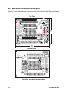
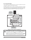
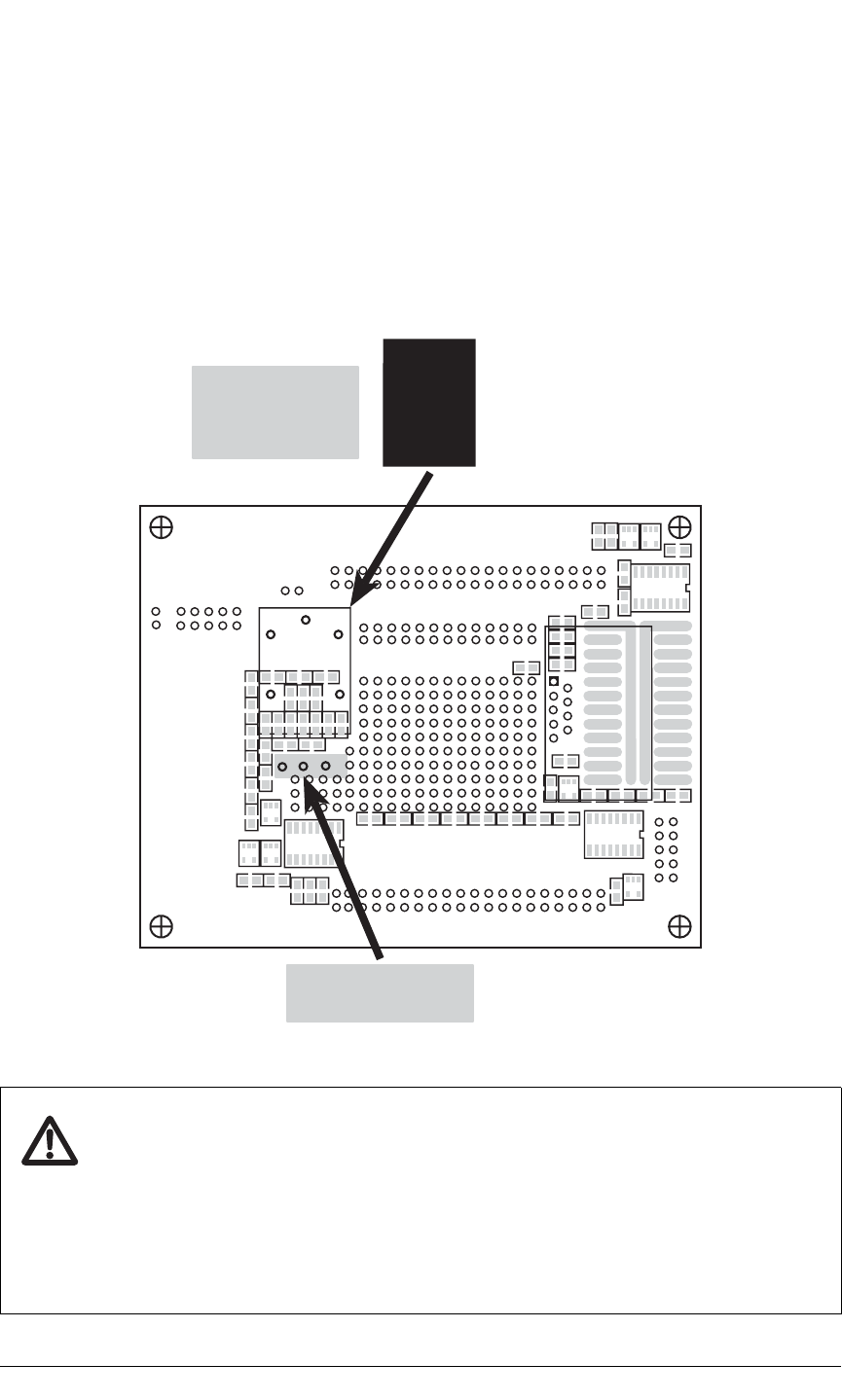
The SPDT relay handles 120 V at 5 A with a 12 V activating coil. The layout to accept this
relay is included on the top side of the Prototyping Board. Note that the relay coil
connec-
tions need to be wired to one of the sinking high-power outputs (HV0–HV2) of the Jackrabbit.
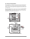
Install the relay on the bottom side of the Prototyping Board, as shown in Figure B-4.
Figure B-4. Installation of Relay on Prototyping Board
NOTE: COIL(+) must be connected to a 12 V power supply when using the relay.
This is the nominal voltage supplied as +RAW when the transformer supplied with the
Development Kit is used, and in this case you may connect COIL(+) to +RAW. If you
use another power supply, connect COIL(+) to +12 V if +RAW is different.
NOTE: If you do use the transformer supplied with the Development Kit for COIL(+),
be aware that its voltage may be as high as 16 V at low current draws. This needs to be
taken into consideration if you plan to use a 12 V relay in critical applications.
Relay Contacts
[0.156" (4 mm) spacing]
[COIL(+) and COIL(-) spacing
is 0.1" (2.5 mm)]
PC2
PC0
TXB
RXB
VCC
RXC
TXC
PC1
PC3
GND
TXC
RXC
J1
RXB
TXB
GND
J7
GND
PA6
PA4
PA2
PA0
PA5
PA3
PA1
PA7
J3
VCC
JP1
DS1
DS2
DS3
DS4
DS5
DS6
DS7
DS8
S1
S2
S3
S4
GND
GND
PB5
PB4
PB3
PB2
PA7
PA6
PA5
PA4
PA3
PA2
PA1
PA0
GND
PE2
PE4
PE6
PE0
HV0
HV2
K
GND
WDO
PB6
PB4
PB2
PB0
GND
VCC
+RAW
HV3
HV1
GND
PE1
PE3
PE5
PE7
PCLK
PB7
PB5
PB3
PB1
GND
BZR
VCC
K
AD0
PD0PE4
POT
+RAW
HV0
COIL(-)
COIL(+)
JP2
N.C.
COM
N.O.
/RST
GND
IOBEN
SM0
VCC
485-
GND
PD6
PD4
PD2
DA0
AD0
PC6
PC4
PD0
PC5
PC7
AGND
DA1
PD1
PD3
PD5
PD7
GND
485+
VCC
SM1
STAT
VBAT
GND
9
5
6
1
J4
Bottom Side
Relay
Connect:
+12 V to COIL(+)
HVx to COIL(-)
K to +RAW


