


DES-3226 NWay Standalone Fast Ethernet Switch User’s Guide
3
IDENTIFYING EXTERNAL COMPONENTS
This chapter describes the front panel, rear panel, side panels, optional plug-in modules, and LED
indicators of the DES-3226.
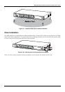
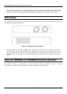
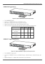
Front Panel
The front panel of the Switch consists of LED indicators, an RS-232 communication port, a slide-in
module slot, and either 10, 18 or 24 MDI-X/MDI-II Ethernet/Fast Ethernet (10/100 Mbps) ports, each
of which is capable of making an uplink connection.
Figure 3-1. Front panel view of the Switch
• Comprehensive LED indicators display the status of the Switch and the network (see the LED
Indicators section below).
• An RS-232 DCE console port for setting up and managing the Switch via a connection to a
console terminal or PC using a terminal emulation program.
• A front-panel slide-in module slot can accommodate a 1-port 100BASE-FX (2Km), 2-port
100BASE-FX (2Km), 1-port 100BASE-FL (15Km), 2-port 100BASE-FL (15Km), 2-port 1000BASE-
SX, 2-port 1000BASE-LX, 2-port 1000BASE-T, or 2-port GBIC module to connect to another
switch, server or network backbone.
• Twenty-four high-performance, NWay Ethernet ports all of which operate at 10/100 Mbps for
connections to end stations, servers and hubs. All ports can auto-negotiate between 10Mbps or
100Mbps and full or half duplex.
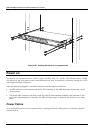
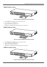
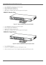
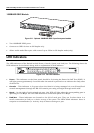
Rear Panel
The rear panel of the Switch contains an AC power connector.
Figure 3-2. Rear panel view of the Switch
8