


DES-3226 NWay Standalone Fast Ethernet Switch User’s Guide
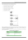
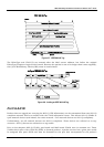
If the packet is not tagged with VLAN information, the ingress port will tag the packet with its own PVID
as a VID (if the port is a tagging port). The switch then determines if the destination port is a member of
the same VLAN (has the same VID) as the ingress port. If it does not, the packet is dropped. If it has the
same VID, the packet is forwarded and the destination port transmits it on its attached network
segment.
This process is referred to as ingress filtering and is used to conserve bandwidth within the switch by
dropping packets that are not on the same VLAN as the ingress port at the point of reception. This
eliminates the subsequent processing of packets that will just be dropped by the destination port.
VLANs
The Switch initially configures one VLAN, VID = 1, called the DEFAULT_VLAN. The factory default
setting assigns all ports on the Switch to the DEFAULT_VLAN. As new VLANs are configured, their
respective member ports are removed from the DEFAULT_VLAN.
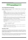
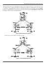
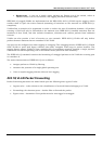
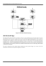
Packets cannot cross VLANs. If a member of one VLAN wants to connect to another VLAN, the link
must be through an external router.
Note: If no VLANs are configured on the switch, then all packets will be forwarded to any
destination port. Packets with unknown source addresses will be flooded to all ports.
Broadcast and multicast packets will also be flooded to all ports.
Note: Each IP interface on the Switch corresponds to a VLAN. The VLAN must be configured before
the IP interface can be setup. The IP interface must have the same name (and the same VID
number) as its corresponding VLAN.
The Switch allows ranges of IP addresses to be assigned to VLANs. Each VLAN must be configured prior
to setting up the corresponding IP interface. An IP addressing scheme must then be established, and
implemented when the IP interfaces are set up on the Switch.
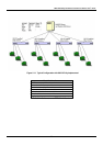
An example is presented below:
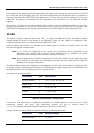
VLAN Name VID Switch Ports
System (default) 1 5, 6, 7, 8, 21, 22, 23, 24
Engineering 2 9, 10, 11, 12
Marketing 3 13, 14, 15, 16
Finance 4 17, 18, 19, 20
Sales 5 1, 2, 3, 4
Table 5-4. VLAN Example – Assigned Ports
In this case, 5 IP interfaces (or 5 subnets) are required, so a CIDR notation of 10.32.0.0/3 (or a 3-bit)
addressing scheme will work. This addressing scheme will give a subnet mask of
11111111.11100000.00000000.00000000 (binary) or 255.224.0.0 (decimal).
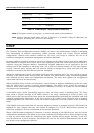
Using a 10.xxx.xxx.xxx IP address notation would give 5 network addresses:
VLAN Name VID Network Address
System (default) 1 10.32.0.0
32