


7
3.0 Operation
This section describes:
• The UPS front panel • Standby mode
• Turning the UPS on and off • Diagnostic tests
• Starting the UPS on battery
3.1 UPS Front Panel
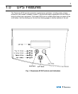
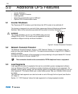
The UPS front panel indicates the UPS status and also identifies potential power problems. Figure
6 shows the UPS front panel indicators and controls.
Figure 6. UPS Front Panel
NOTE
If the alarm beeps or if the indicator is on, see Table 10 in Section 9.0 to identi-
fy and correct the problem. To configure parameters through the front panel, see Section
4.0 "Configuration".
Display Mode
To view the UPS current settings, press the
↵↵
button for one second and release. Use the
↵↵
button to scroll through the list of settings, which appear in the following order:
LCD Message Description
I/P VOLT= xxx.xV Input voltage.
I/P FREQ= xx.xHZ Input frequency.
O/P VOLT= xxx.xV Output voltage.
O/P FREQ= xx.xHZ Output frequency.
O/P Load = x% Approximate percentage of UPS load capacity being used
by the protected equipment.
O/P Watt= xW Output watts.
O/P VA= xVA Output VA.
O/P Cur= x.xA Output current.
BAT VOLT= xx.xV Battery voltage.
BAT CHARGE= xxx% Approximate percentage of battery capacity remaining.
BackUp Time= xxxM Approximate battery time remaining in minutes. The display
changes to seconds after one minute (Backup Time= xxxS).
CPU Version x.xx Firmware revision level.
NOTE The UPS exits Display mode automatically after five seconds if the
↵↵
button is not pressed. To
lock the meter screen, press the
↵↵
button until a beep is heard (3 seconds) then release it. To unlock
the display, press the button until a beep is heard, then release it.