


Chapter 1 General Description 1
HIPULSE U UPS Single Module And “1+N” (Expandable) 160/200/300/400kVA User Manual
Chapter 1 General Description
This chapter briefly introduces the features, design concept and operation mode of the HIPULSE U UPS.
1.1 Features
The HIPULSE U UPS is connected between a critical load, such as a computer, and its 3-phase mains power supply.
Being designed to furnish a well regulated 3-phase output power supply under all rated load and input supply
conditions, the system offers the user the following advantages:
z increased power quality
The UPS has its own internal voltage and frequency regulators which ensure that its output is maintained
within close tolerances independent of voltage and frequency variations on the mains power lines.
z increased noise rejection
By rectifying the input AC power to DC power, and then converting it back to AC power, any electrical noise
present on the input mains supply line is effectively isolated from the UPS output, therefore the critical load
sees only clean power.
z power blackout protection
If the mains power fails, the UPS continues to power the critical load from its battery source, leaving the load
immune from power disturbances.
1.2 Design Concept
1.2.1 HIPULSE U Module Design
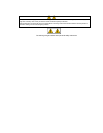
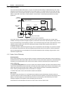
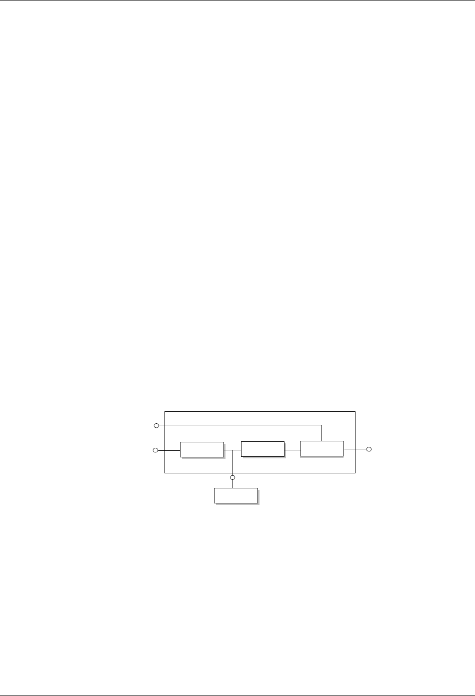
This section describes the operating principle of an individual module. The UPS basically operates as an AC-DC-AC
converter (see Figure 1-1). The first conversion stage (from AC to DC) uses a 3-phase, fully controlled
silicon-controlled resistor (SCR) bridge rectifier to convert the incoming mains supply into a regulated DC busbar.
Rectifier
Inverter
Static switch
Battery
Bypass AC
supply
Rectifier
AC supply
UPS AC
output
Figure 1-1 Single module block diagram
The DC busbar produced by the rectifier provides both battery charging power – being equipped with a temperature
compensated battery charging system, to prolong battery life – and power to the inverter section – which utilizes the
latest integrated gate bipolar transistor (IGBT) switching space vector pulse width modulation (SVPWM) design – and
provides the second conversion phase, that is, reconverting the DC busbar voltage back into an AC voltage
waveform.
During normal operation, both the rectifier and inverter sections are active and provide regulated load power whilst
simultaneously charging the battery. In the event of a mains power failure, the rectifier becomes inoperative and the
inverter is powered solely from the battery. Critical load power is maintained under these conditions until the battery is
fully discharged, whereupon the UPS shuts down. The end of battery discharge is assumed when the battery voltage
falls below a preset value (that is, 330Vdc for a 400Vac system).
The period for which the load can be maintained following a mains power failure is known as the system’s “Autonomy
Time” and is dependent upon both the battery A/Hr capacity and the applied percentage load.