


Chapter 3 Electrical Installation 15
HIPULSE U UPS Single Module And “1+N” (Expandable) 160/200/300/400kVA User Manual
Chapter 3 Electrical Installation
This chapter introduces the electrical installation of the HIPULSE U UPS, including the procedures or methods for
power cabling and control cabling, and the distance from floor to connection point.
The UPS requires both power cabling and control cabling once it has been mechanically installed. All control cables,
whether screened or not, should be run separate from the power cables in metal conduits or metal ducts which are
electrically bonded to the metalwork of the cabinets to which they are connected.
3.1 Power Cabling
Warning
BEFORE CABLING UP THE UPS, ENSURE THAT YOU ARE AWARE OF THE LOCATION AND OPERATION OF THE
EXTERNAL ISOLATORS THAT CONNECT THE UPS INPUT/BYPASS SUPPLY TO THE MAINS DISTRIBUTION PANEL.
CHECK THAT THESE SUPPLIES ARE ELECTRICALLY ISOLATED, AND POST ANY NECESSARY Warning SIGNS TO
PREVENT THEIR INADVERTENT OPERATION.
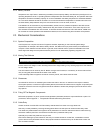
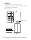
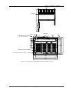
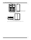
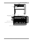
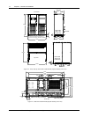
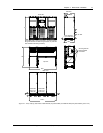
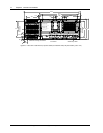
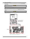
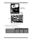
For cable entry, refer to 2.3.5 Cable Entry.
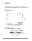
3.1.1 System Configuration
The power cables of the system must be size with respect to the following description:
Module input cables
The input cables must be sized for the maximum input current, including the maximum battery recharge current,
given in the Table 3-1, with respect to the module rating and the input AC voltage.
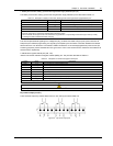
Module bypass and output cables
The bypass and output cables must be sized for the nominal output current, given in the Table 3-1, with respect to the
module rating and the output AC voltage.
Battery cables
Each UPS module has its own battery which is connected using two cables, one positive and one negative. The
battery cables must be sized for the battery discharge current at the end-of-discharge voltage, as given in Table 3-1
with respect to the module rating.
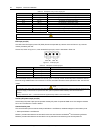
3.1.2 Cable Rating
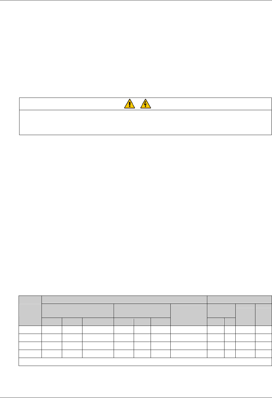
The power cables can be sized to suit the UPS module rating according to Table 3-1.
Table 3-1 UPS module power cable rating
Nominal current: Amps Busbar stud size
Input mains with full battery recharge
(subtract 5% for 12-pulse)
Bypass/output at full load
Input/output
cables
UPS rating
(kVA)
380V 400V 415V 380V 400V 415V
Battery at
minimum battery
voltage (400Vac)*
Bolt Ø
Battery
cables
Torque
(Nm)
160 341 324 312 243 231 222 464 M10 11 M10 bolt 26
200 426 405 390 304 289 278 580 M10 11 M10 bolt 26
300 634 602 572 456 434 413 870 M12 13 M12 bolt 50
400 848 803 772 607 578 556 1160 M12 13 M12 bolt 50
Note*: Maximum battery discharge current at 380Vac supply increases by 3%, and for a 415Vac supply decreases by 3%