


48 Chapter 6 Battery
HIPULSE U UPS Single Module And “1+N” (Expandable) 160/200/300/400kVA User Manual
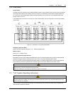
6.6 Battery Protection
The battery is connected to the UPS through a BCB which is manually closed and electronically tripped through the
UPS control circuitry. If the cells are rack-mounted (or located remote from the main UPS cabinet), the BCB must be
mounted as near as possible to the batteries themselves, and the power and control cables connected to the UPS
using the most direct route possible.
Features of the BCB include:
z Isolation from battery to achieve safety and reliability
z Shortcircuit protection
z Automatic opening in the event of inverter lockup due to battery undervoltage to prevent battery damage caused
by overdischarge
z Tripping by remote emergency power off (EPO) button if installed
z Operation error protection
To achieve the required autonomy time, it may be necessary to parallel battery strings. In which case, the battery
circuit breaker should be placed downstream of all parallel battery strings.
Note: All equipment servicing procedures should be carried out only by trained personnel.
6.7 Battery Connection
6.7.1 Fitting The Batteries
1. In general a minimum space of 10 mm must be left on all vertical sides of the battery block to permit free air
movement around the cells.
2. A clearance of 150 mm should be allowed between the top of the cells and the underside of the shelf above (this is
necessary for monitoring and servicing the cells).
3. When installing the batteries always work from the bottom shelf upwards to prevent raising the center of gravity.
6.7.2 Connecting The Battery
1. All cabinets (or racks) must be earthed.
2. In general it is recommended that the inter-connecting cables be fitted to the batteries within their particular level
before fitting the inter-level connecting cables, followed finally by the cables to the circuit breaker.
3. An insulating shroud should be fitted to each terminal after its connection has been made.
4. When connecting the cables between the battery extremities to the circuit breaker always connect the circuit
breaker end of the cable first.
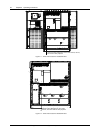
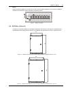
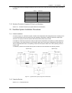
6.8 Battery Installation
Whatever the type of mounting system selected, the following conditions should be noted (see Figure 6-1):
X Layout of cells:
Whatever battery mounting system is used, the batteries should be laid out in such a manner as to make
simultaneous contact with two exposed live parts having a potential greater than 150V impossible. Where this is not
possible, insulated terminal shields must be installed and insulated cables must be used for connections.
Y Service platform:
The service platform (or duckboard) must be slip-proof, insulated from the floor and be at least one meter wide.
Z Connections:
All connections must be as short as possible.