


28 Chapter 4 Operator Control And Display Panel
HIPULSE U UPS Single Module And “1+N” (Expandable) 160/200/300/400kVA User Manual
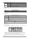
LED State Description
Steady green UPS output ON and normal
Steady red UPS output ON and overloaded
Load LED
OFF UPS output OFF
Steady green Normal operation
Steady yellow UPS warning (for example, AC input failure)
Alarm LED
(STATUS)
Steady red UPS fault (for example, fuse or hardware failure)
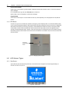
4.1.2 Buzzer
The operator control and display panel provides a buzzer. UPS activity is accompanied by the following sounds.
Table 4-2 Audible alarm description
Single beep Direct access key acknowledgement
One beep per second UPS warning. For example, AC input failure
Continuous beep Fault. For example, fuse or hardware failure
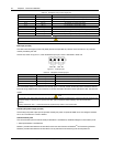
4.1.3 Control Buttons
The operator control and display panel provides four control buttons, as described in Table 4-3.
Table 4-3 Description of control buttons
Control button Description
INVERTER ON
Pushing this button turns on the inverter.
Note: If the inverter is not ready, pushing this button cannot turn on the UPS
INVERTER OFF During UPS operation, pushing this button turns off the inverter and transfers the load to the bypass
FAULT CLEAR
In case the UPS shuts down due to fault, after eliminating the alarm conditions, pushing this button clears
the fault
SILENCE
ON/OFF
When an alarm is active, pushing this button silences the audible alarm. When a new alarm occurs
afterwards, the buzzer will give audible alarm again. When there is no audible alarm, pushing this button
initiates the audible alrm test
Note
To activate the above control buttons, you are required to press and hold the buttons for approximately 2 seconds until a beeping
sound is heard.
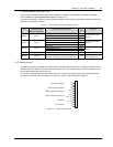
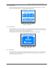
4.1.4 LCD And Menu Keys
The operator control and display panel provides an LCD and five menu keys (F1, F2, F3, F4, HELP). The menu keys
are described in Table 4-4.
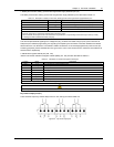
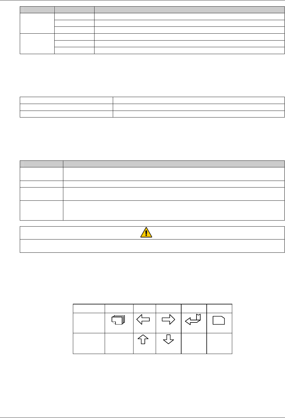
Table 4-4 Menu key icons and their meaning
Key F1F2F3F4
ESC
?
Shift
Escape
Left
Up
Right
Down
Enter
Help
HELP
Function 1
Function 2
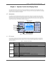
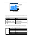
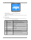
The user-friendly and menu-driven LCD allows you to easily browse through the input, output, load and battery
parameters, learn current UPS status and alarm information, perform functional setting and control operation. The
LCD also stores up to 512 historical records that can retrieve for reference and diagnosis.
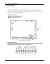
As shown in Figure 4-2, the LCD primary screen is divided into five windows: system information window, menu
window, UPS data window, and current record window. Pressing the F1 key scrolls through the user-operable
windows.