


Chapter 5 Operating Instructions 41
HIPULSE U UPS Single Module And “1+N” (Expandable) 160/200/300/400kVA User Manual
5.2 Start-Up Procedure (Into Normal Mode)
This procedure must be followed when turning on the UPS from a fully powered down condition, that is, where the
load is not being initially supplied at all or where supplied by the maintenance bypass switch. It is assumed that the
installation is complete, the system has been commissioned by authorized personnel and the external power isolators
are closed.
Warning – Mains voltage will be applied to UPS output terminals
This procedure results in mains voltage being applied to the UPS output terminals.
Isolate and attach warning labels to any downstream load connections, as applicable.
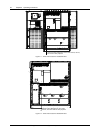
1. Open the UPS door to gain access to the power switches.
2. Close the bypass switch Q2 and output switch Q5. Close also any external output isolation switches, where used.
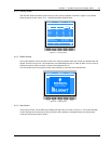
The LCD display becomes active and after initialization, the UPS output is powered from the bypass. At this point, the
status of the LEDs is as described in Table 5-1.
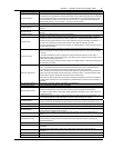
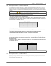
Table 5-1 LED status
LED Status
Bypass LED Steady green
Load LED Steady green
Battery LED Steady red
Alarm LED Steady yellow
3. Close the input switch Q1.
The rectifier LED flashes during the startup of rectifier and becomes steady green once the rectifier reaches normal
operation state after about 15s.
4. Verify the bus voltage and the battery polarities, and close the BCB, which is located in the BCB box.
5. Following battery availability being detected by the UPS, the red battery LED extinguishes.
6. Open (or confirm open) the internal maintenance bypass switch Q3.
7. Press and hold the INVERTER ON button for two seconds.
The inverter will start up and the inverter LED flashes while it synchronizes to the bypass voltage frequency.
After the inverter is ready, the UPS transfers from bypass to inverter, the bypass LED turns off, and the inverter LED
becomes steady green.
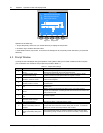
8. Check that no “Warning” message is displayed in the top right corner of the LCD screen and the status of the LEDs
is as described in Table 5-2.
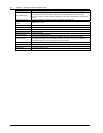
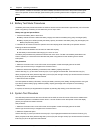
Table 5-2 LED status
LED Status
Rectifier LED Steady green
Bypass LED Off
Battery LED Off
Inverter LED Steady green
Load LED Steady green
Alarm LED Off
The UPS is now operating in Normal mode
5.3 Start-Up Procedure (Into ECO Mode)
Apply only to a single module UPS and when programmed by the commissioning engineer to perform ECO mode
control of the power delivered to the load.