


Chapter 7 “1+N” System 53
HIPULSE U UPS Single Module And “1+N” (Expandable) 160/200/300/400kVA User Manual
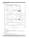
7.2.5 Control Cables
Parallel Cable
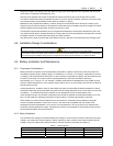
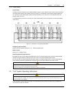
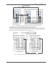
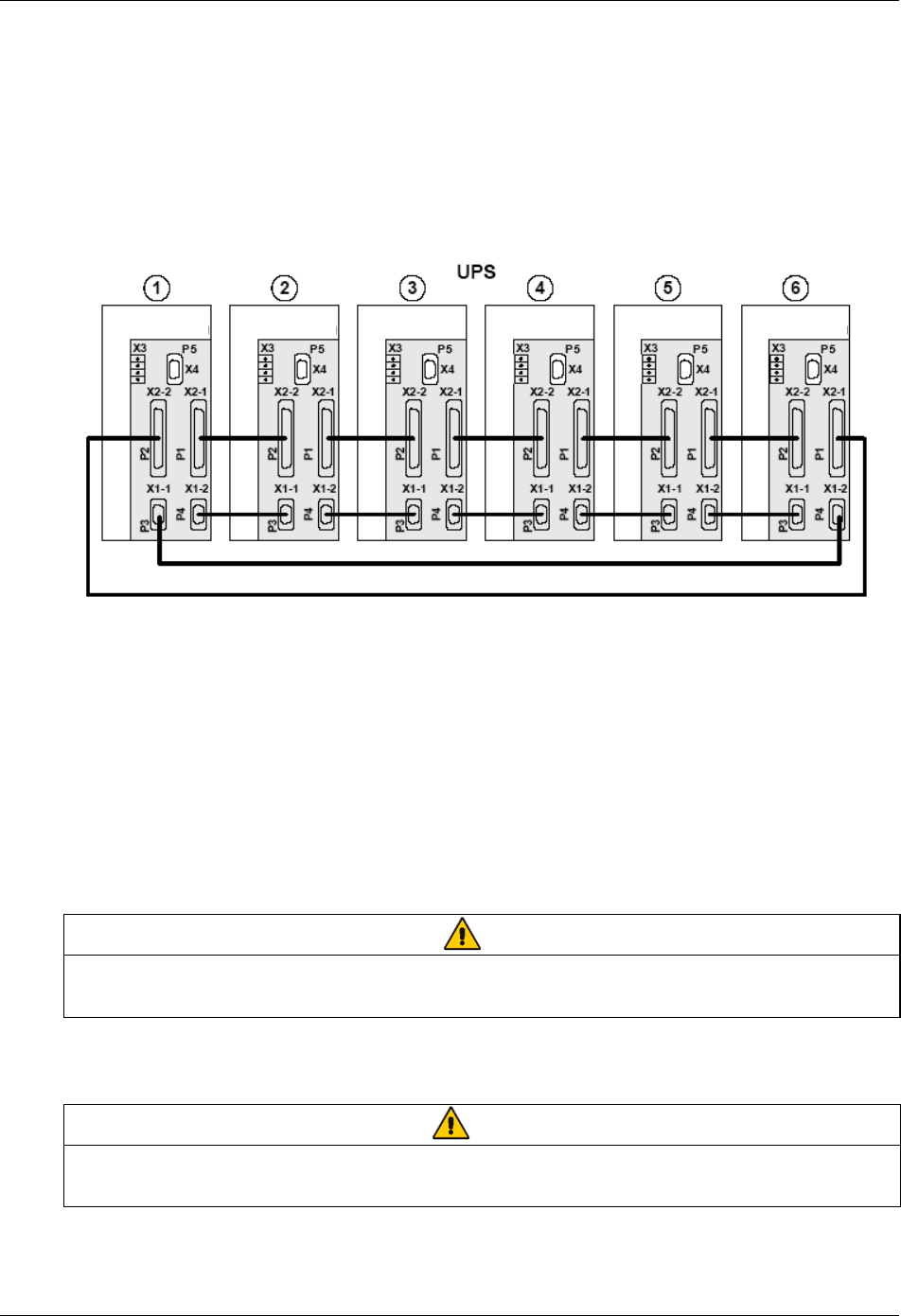
Shielded and double insulated control cables available in length up to 20 meters must be must be interconnected in a
ring configuration between UPS modules as shown in Figure 7-2. Specifically, connect the two parallel cables from
X1-1 and X2-2 on the parallel board of the first module respectively to X1-2 and X2-1 on the parallel board of the
second module, and so on.
The parallel board is mounted on the inner door of each UPS module. The ring configuration ensures high reliability
of the control.
Parallel board
Parallel board
Parallel board
Parallel board Parallel board
Parallel board
Figure 7-2 Connection of “1+N” system parallel cables
Emergency power off (EPO)
Refer to the EPO input port (X2) part in 3.3.1 Monitoring Board Ports.
Battery control
Refer to 3.3.2 Battery Control.
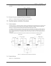
External bypass and output interlock
EXT-Maint (X3-1&2) on UPS parallel board M3 (leave open if no external bypass switch is used) provides external
maintenance bypass interlock protection for the UPS. Short circuit means external bypass closed.
EXT-Out (X3-3&4) on UPS parallel board M3 (leave shorted if no external output switch is used) provides external
output interlock protection for paralleled UPS modules. Short circuit means external output switch closed.
Note
UPS parallel board M3 is located behind protective covers accessible aftr opening the UPS front door — removal of this barrier
requires the use of a tool and is restricted to service personnel.
Jumper JP1 (located next to X3) needs to be removed for X3: 3&4 to work properly.
7.3 “1+N” System Operating Instructions
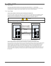
Warning
If residual current detectors (RCDs) are used on UPS unit inputs, use a common device only on the system’s bypass mains. At
the instant of electrical connection, the current may not be split instantaneously and this may cause the residual current circuit
breakers (RCCBs) to trip separately.
These operations must be performed one at a time, progressing to the next step only after having completed the
previous step on both UPS modules.