


Chapter 2 Mechanical Installation 7
HIPULSE U UPS Single Module And “1+N” (Expandable) 160/200/300/400kVA User Manual
2.2.2 Battery Location
Temperature is a major factor in determining the battery life and capacity. Battery manufacturers quote figures for an
operating temperature of 20°C. Operating above this temperature will reduce the battery life, and operation below this
temperature will reduce the battery capacity. On a normal installation the battery temperature is maintained between
15°C and 25°C. Batteries should be mounted in an environment where the temperature is consistent and even over
the whole battery. Keep batteries away from main heat sources or main air inlets, and so on.
The batteries can be mounted in a purpose-built battery cabinet, which is positioned adjacent to the UPS module.
Pedestals are required for the battery cabinets when they are located on raised floors, in the same way as for the
UPS cabinets If the batteries are rack-mounted, or otherwise located remote to the main UPS cabinet, a BCB must
be mounted as close as possible to the batteries themselves, and connected using the most direct route possible.
2.3 Mechanical Considerations
2.3.1 System Composition
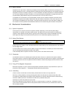
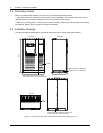
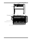
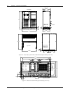
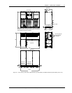
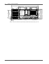
A UPS system can comprise a number of equipment cabinets, depending on the individual system design
requirements, for example, UPS cabinet, battery cabinet. The 300kVA UPS (12-pulse rectifier) and 400kVA UPS
comprise a main cabinet and a side cabinet. In general, all the cabinets used in a particular installation are of the
same height and designed to be positioned side-by-side to form an aesthetically appealing equipment suit.
2.3.2 Moving The Cabinets
Warning
Ensure that any lifting equipment that used in moving the UPS cabinet has sufficient lifting capacity.
Ensure that the UPS weight is within the designated surface weight loading of any handling equipment. See Table 8-3
for UPS weight details.
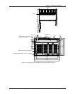
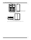
The UPS cabinet can be moved by fork lift. Before moving the UPS cabinet, it is necessary to remove both the front,
rear (or side) grille panels located at the base of the cabinet.
In the eventuality that the equipment cannot be moved by fork lift, then rollers should be used.
2.3.3 Clearances
As HIPULSE U UPS has no ventilation grills at either the sides or the rear, no clearances are required. However,
where space permits, a clearance of approximately 600mm at the back will ease access to magnetic component parts.
Clearance around the front of the equipment should be sufficient to enable free passage of personnel with the doors
fully opened.
2.3.4 Fixing Of The Magnetic Components
Before the equipment is in place, remove the transportation restraints that hold the output transformer in place. For
procedures, refer to Appendix 1 Transportation Restraints Removing Procedures.
2.3.5 Cable Entry
Cables can enter for HIPULSE U UPS and battery cabinet either from below or through either side.
Side entry is made possible by removing blanking pieces fitted in the side panel to reveal the cable entry holes.
This cable entry method allows the equipment to be positioned on a solid floor without the need for cable trenching
and allows cables to pass from one module to the other when positioned side-by-side.
Optionally a top cable entry extension may be used.
Note: When selecting the power cables for side entry to a module located on a solid floor, consideration must be
given to the minimum permissible radius of the proposed cables to ensure that they can be fashioned to reach the
UPS connection busbars.