


24 Chapter 3 Electrical Installation
HIPULSE U UPS Single Module And “1+N” (Expandable) 160/200/300/400kVA User Manual
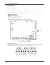
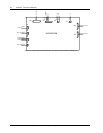
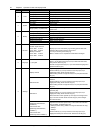
Table 3-8 Description of auxiliary terminal block X3
X3 terminal reference Reference label Description
1 FB BCB normally open auxiliary contact
2 GND Signal ground
3 OL Cable detection
4 +12V Power positive
5 TMP_T Temperature sensing terminal
6 GND Temperature sensing signal ground
7 LM355+ LM335 detection positive
8 LM355+GND LM335 signal ground
9 DRV BCB drive
10 DRV_GND Drive ground
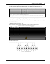
Note:
1. The auxiliary cables of the battery must be screened and double insulated.
2. The screen is connected to the earth of the battery cabinet or supporting rack.
3. Use multiple-core shielded cables with a section of 0.5 to 1 mm
2
.
4. Connect the cables with the fast-on 6.3*0.8 mm terminals (female)
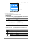
Connect the BCB control and temperature compensation cables between the UPS auxiliary terminal block X3 and
BCB control board. For details, refer to Figure 6-5. These cable must be shielded, shield should be connected at
protective earth of battery cabinet or battery breaker, not of UPS.
Note
If battery temperature compensation is needed, this function must be activated by the commissioning engineer.
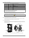
3.4 Connecting Main Cabinet And Side Cabinet
The 300kVA UPS (12-pulse rectifier) and 400kVA UPS comprise a main cabinet and a side cabinet.. In installation,
you need to make electrical connection between the main cabinet and side cabinet.
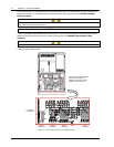
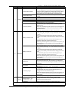
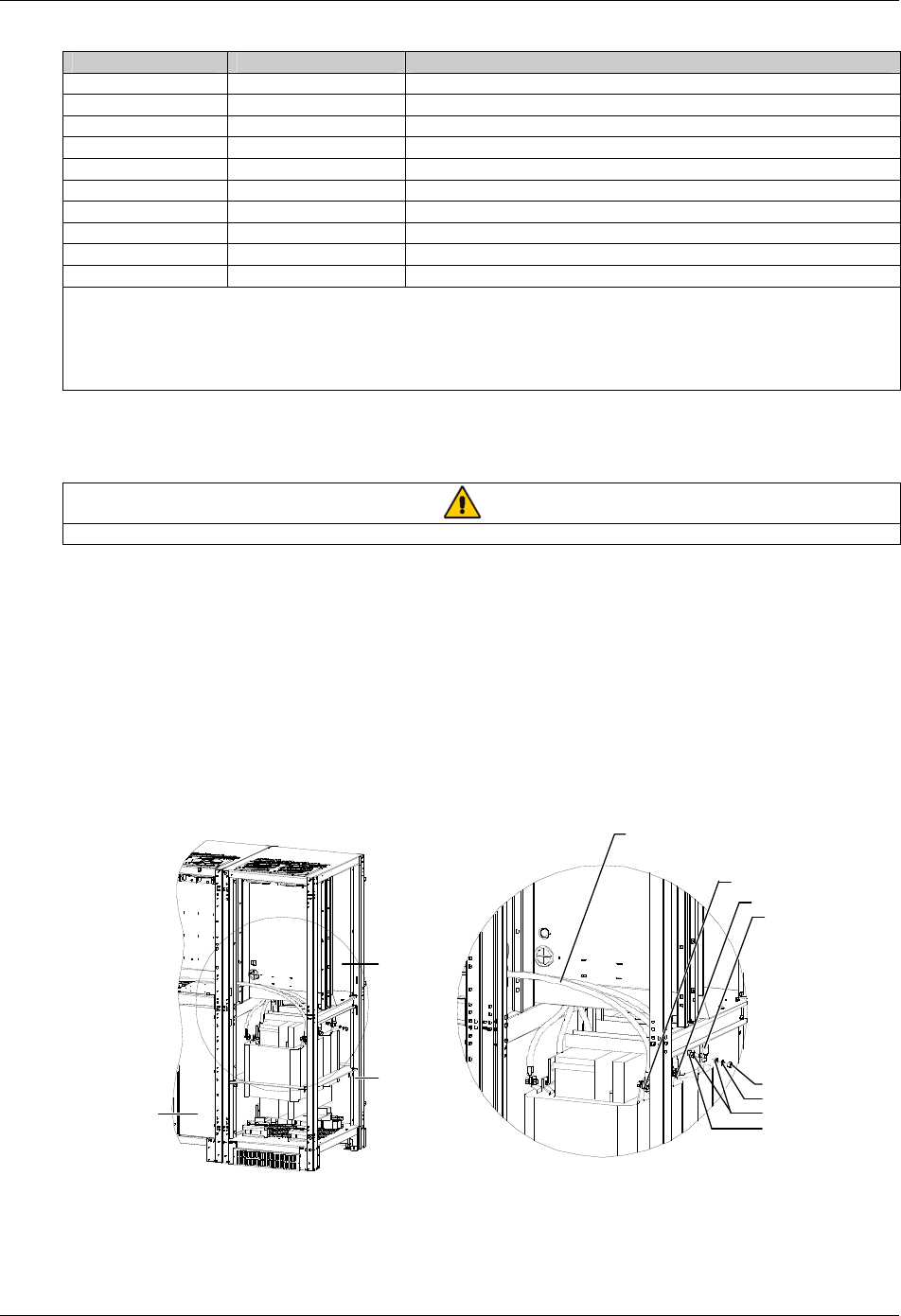
3.4.1 Connecting Power Cables
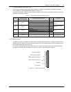
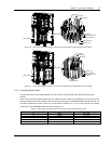
The power cable connections between the main cabinet and side cabinet of the 300kVA UPS (12-pulse rectifier) and
400kVA UPS are shown in Figure 3-9 to Figure 3-11. The installation engineer should make cable connection in strict
accordance with these figures.
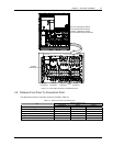
A
W4-2, W5-2, W6-2
W4-2
W5-2
W6-2
Side cabinet
Main cabinet
Nut M10
Spring w asher 10
Plain washer 10
Bolt M10 *35
A amplified view
Figure 3-9 Power cable connection between main cabinet and side cabinet of 300kVA UPS (12-pulse rectifier)