


Operator Control Panel and Display
93
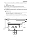
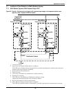
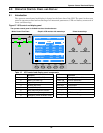
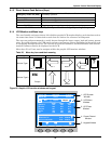
8.1.1 Mimic Power Flow
The LED mounted on the mimic flow chart represent the various power paths and current UPS oper-
ational status.
8.1.2 Audible Alarm (Buzzer)
UPS activity is accompanied by the following sounds
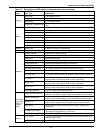
Table 13 Rectifier indicator—1
Green Rectifier in Normal Operation
Flashing
Green
Input AC Normal, but rectifier not operating
Red Rectifier Failed
Off Rectifier Not operating, Input AC Not Available or out of normal range
Table 14 Battery indicator—2
Green Battery Normal, but discharging and powering the load
Flashing
Green
Battery End of Discharge pre-warning
Red
Battery abnormal (Failed, Absent or Polarity Reversed) or Battery
Converter abnormal
(Failed, overcurrent, overtemperature)
Off Battery and Converter Normal, Battery charging.
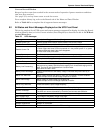
Table 15 Bypass indicator—3
Green Load on Bypass power
Red Bypass not available, out of normal range or Static bypass switch fault.
Off Bypass Normal, load not on bypass
Table 16 Inverter indicator—4
Green Inverter Normal and powering the load
Flashing
Green
Inverter ON, starting up, synchronising,
or standing by (ECO mode)
Red Inverter failed
Off Inverter not operating
Table 17 Load indicator—5
Green UPS output ON and Normal
Red UPS output ON and Overloaded
Off UPS output OFF.
Table 18 Status (Alarm) indicator—6
Green Normal Operation
Yellow UPS Warning e.g. AC Input Failure
Red UPS fault e.g. Fuse or Hardware failure
Table 19 Audible alarm key
Single beep Direct Access key acknowledgement
One beep
per second
UPS Warning e.g. AC Input Failure
Continuous
beep
Fault e.g. Fuse or Hardware failure