


UPS Multi-Module Installation
50
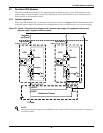
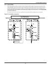
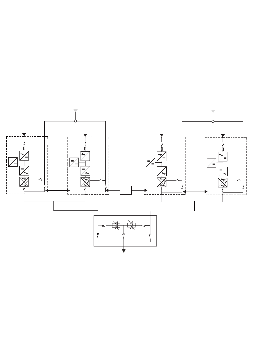
3.4 Dual Bus System
3.4.1 Cabinet Installation
The Dual Bus System consists of two independent UPS configurations each consisting of one or more
UPS modules. Dual Bus Systems are high availability configurations suitable for loads with multiple
input terminals. For single input loads an optional Static Transfer Switch may be added and the stan-
dard Load Bus Synchroniser activated. Depending on the configuration, follow the appropriate instal-
lation instructions for each system.
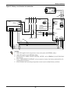
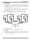
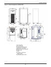
Place the UPS modules side by side and interconnect as shown below.
The objective of the Dual-bus Synchronizer (DBS) is to keep the output of two independent UPS sys-
tems (or parallel systems) in synchronization. One system is designated as the master; the other is
designated as the slave. The operating modes covered comprise master and or slave operating
inverter or bypass mode.
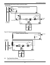
Figure 33 Typical dual bus system configuration with static transfer switch and Load Bus Synch
3.4.2 External Protective Devices
Refer to the instructions supplied in 1.0 - Single Module UPS Installation.
3.4.3 Power Cables
The wiring of power cables is similar to that of single module system. The Bypass and the Main input
sources must be referenced to the same neutral potential and input earth leakage monitoring devices,
if installed, must be located upstream of the common neutral sinking point. Refer to the instructions
in 1.0 - Single Module UPS Installation
STS
Load
UPS1
Q1
CHARGER
RECTIFER
INVERTER
Q5
Q3
Q2
UPS1
Q1
CHARGER
RECTIFER
INVERTER
Q5
Q3
Q2
LBS
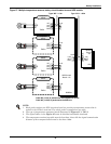
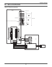
Input
Rectifier
Input
Rectifier
Bypass Supply
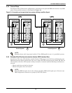
UPS1
Q1
CHARGER
RECTIFER
INVERTER
INTERMODULE
CONTROL CABLE
Q5
Q3
Q2
UPS1
Q1
CHARGER
RECTIFER
INVERTER
Q5
Q3
Q2
Input
Rectifier
Input
Rectifier
Bypass Supply
INTERMODULE
CONTROL CABLE