


UPS Multi-Module Installation
46
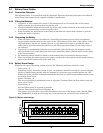
3.2 Paralleled UPS Modules
The basic installation procedure of a parallel system comprising two or more UPS modules is the
same as that of single module system. The following sections only introduce the installation proce-
dures specific to the parallel system.
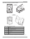
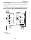
3.2.1 Cabinet Installation
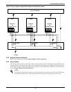
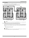
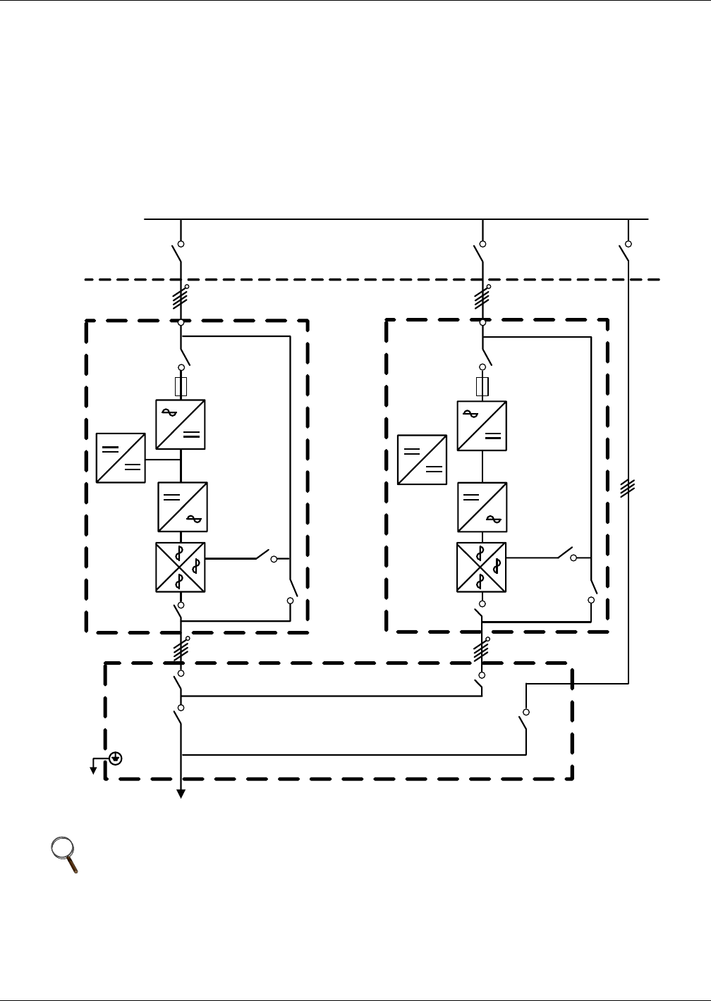
Place the UPS modules side by side and interconnect as shown in Figure 29. The distribution panel
(external bypass cabinet) is optional but recommended for ease of maintenance and system testing.
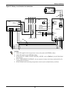
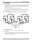
Figure 29 Typical 1+N system block diagram with common input supply, with separate batteries and
optional output / bypass distribution panel
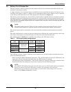
NOTE
Internal maintenance bypass switch Q3 must be removed when the load exceeds the capacity of
one UPS module.
To Load
Distribution Cabinet
Supplied
by Others
Input Mains
Supply L1, L2, L3, N
UPS1
UPS2
Q1
Rectifier
Inverter
Charger
Q2
Q3
Q5
Q2
Q3
Q5
Rectifier
Inverter
Charger
Q1
Input Mains
Supply L1, L2, L3, N
L1, L2, L3, NL1, L2, L3, N
QUPS
QBYP
Q1EXT Q2EXT