


Options—For Assembly Inside the UPS Cabinet
112
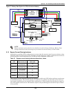
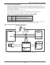
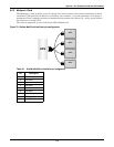
9.2.2 Relay Card
The Relay card provides voltage-free contact closures for remote monitoring of alarm conditions.
Delivering On Battery, On Bypass, Low Battery, Summary Alarm, UPS Fault and On UPS signals,
the easy-to-install card integrates with AS/400 computers (additional cable required) and other relay
contact monitoring systems.
The Relay card is rated for 24 VAC/VDC at 1A and supported in any of the three NX Intellislot bays.
**A Summary Alarm occurs when any of the following conditions exist:
• Utility power is out of the acceptable range (voltage and/or frequency)
• UPS is in BYPASS MODE (load not on Inverter power)
• UPS Battery is LOW
• UPS fault has occurred
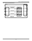
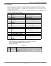
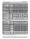
Table 28 Relay Card pin configuration
Pin
Function Operation
1 UPS Fault Closed if no UPS failure
2-3 Not Used
4 UPS Fault Closed if UPS fails
5 Summary Alarm** Closed if SUMMARY ALARM** occurs
6 Summary Alarm** Closed if no alarm conditions are present
7 Any Mode Shutdown return Not – use External EPO terminal
8 Not Used
9 Common - Low Battery
10 Low Battery Closed if battery is OK
11 Low Battery Closed if LOW BATTERY point occurs.
12-13 Not Used
14 UPS Any Mode Shutdown Not support– use External EPO terminal
15 On UPS Closed if ON UPS (inverter) power
16 On Battery Closed if ON BATTERY power (Utility failure)
17 Common - UPS Fault, Summary Alarm,
On UPS, On Battery, On Bypass
18 On Battery Closed if not ON Battery power (Utility OK)
19
÷ 23 Not Used
24 On Bypass Closed if ON BYPASS
25 Not Used
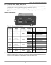
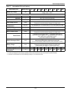
Table 29:
#
Connection Description
JP01 Pin 9 to Pin 17 Allows all relay COMMONS to be tied together.
JP02 Pin 7 to Pin 17
REMOVE - (Interconnects all relay COMMONS and the (not supported)
ANY MODE SHUTDOWN Return.