


Installation Drawings
63
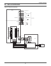
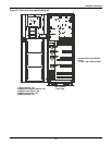
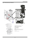
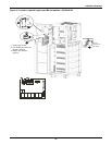
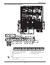
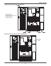
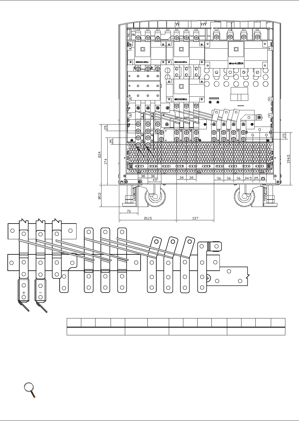
Figure 48 Cable terminal layout—60-80kVA NX
1. Main (Rectifier) connections (N1-U1-V1-W1)
2. Bypass connections (N1-U3-V3-W3)
3. Output connections (N2-U2-V2-W2)
4. Battery connections (+ / -)
5. Earth
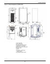
6. Mains Input isolator (Q1)
7. Bypass Input isolator (Q2)
8. Maintenance bypass isolator (Q3)
9. Output isolator (Q5)
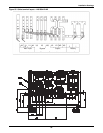
U1 V1 W1 N1 Batt + Batt - N1 U3 V3 W3 U2 V2 W2 N2
Input Batt Bypass Output
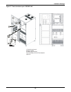
NOTE
1. For split bypass operation, ensure that the busbars (*) between bypass and rectifier
input are removed.
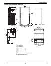
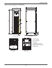
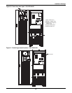
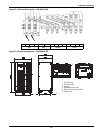
2. All dimensions are in millimeters.
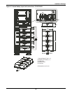
U1 V1 W1
U3 V3 W3
N1 N2
U2 V2 W2
PE