


Single Module UPS Installation
14
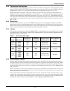
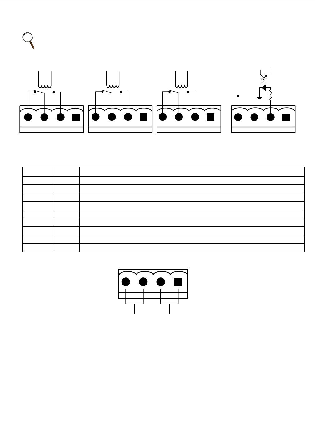
1.8.4 Output Dry Contacts
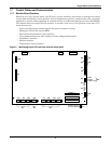
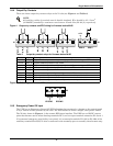
There are three output dry contact relays at the X1 slot (see Figure 4 and Table 6)
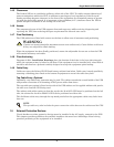
Figure 4 Output dry contacts and EPO wiring for firmware before M162
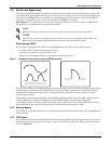
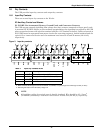
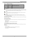
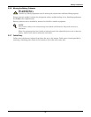
Figure 5 EPO wiring for firmware M200 or later
1.8.5 Emergency Power Off Input
The UPS has an Emergency Power Off (EPO) function that operates by a button on the control panel
or by a remote contact provided by the user. The EPO button is under a hinged, clear plastic shield.
The X2 slot, shown in Figure 4, is the remote EPO input interface. The EPO has an NO/NC contact
point that becomes active when shorting terminals X2: 3 and 4 or open terminal connection X2: 2 and 1
If an external emergency stop facility is required, it is connected terminals X2: 1&2 or X2: 3&4 of the
auxiliary terminal block (X2). It also is connected to the normally open or normally closed remote stop
NOTE
All auxiliary cables of terminal must be double-insulated. Wire should be 0.5-1.5mm
2
(16-20AWG) stranded for maximum runs between 25 and 50m (82-164 ft.) respectively.
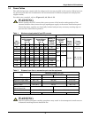
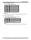
Table 6 Output dry contact relays for firmware before M162
Position Name
Description
J13.2 BFP_O Bypass feedback protection relay; normally open. Closed when bypass SCR is shorted.
J13.3 BFP_S Bypass feedback protection relay center
J13.4 BFP_C Bypass feedback protection relay; normally closed. Open when bypass SCR is shorted.
J21.2 INV_O Inverter mode relay; normally open. Closed when UPS is in inverter mode.
J21.3 INV_S Inverter mode relay center
J21.4 INV_C Inverter mode relay; normally closed. Open when UPS is in inverter mode.
J25.2 ACF_O Main input fault relay; normally open. Closed when main input is in fault.
J25.3 ACF_S Main input fault relay center
J25.4 ACF_C Main input fault relay; normally closed. Open when main input is in fault.
EPO-LEPO-H
X2X1
BFP_C
J21 J25 J25
BFP_S
BFP_O
INV_O
INV_S
INV_C
ACF_C
ACF_S
ACF_O
+12V
J13
J28
X2
EPO-NO EPO-NC